KEY TAKEAWAYS FOR INDUSTRIAL BUYERS
- Recessed Concave Profile: Structural concave lens design protects the illumination surface of the light indicator from mechanical scrapes and accidental operator contact.
- Heavy-Duty Metallic Housing: Precision-machined metal casing provides far higher impact resistance, flame retardancy, and chemical immunity than plastic signal lamps.
- Pre-Wired 2PIN Termination: Factory-installed wire leads eliminate manual terminal soldering, drastically reducing cabinet assembly time for bulk light indicator installation.
- IP65 Ingress Protection: Outfitted with a durable silicone sealing washer that creates a dust-tight, splash-proof seal against harsh outdoor and washdown environments.
- Broad Custom Voltage Support: Every light indicator can be customized with internal drop resistors to support 3V, 6V, 12V, 24V, 36V, 110V, and 220V AC/DC electrical systems.
- Global Safety Certifications: Full compliance with UL (Certificate Number: E498776), CE, VDE, RoHS, CCC, and ISO9001 streamlines export certification for OEM machinery.
- Vibration-Proof Mounting: Single-nut rear locking mechanism with a spring washer prevents physical loosening on high-vibration equipment panels.
- Direct Manufacturer Support: Sourcing your light indicator order direct from FILN guarantees custom cable lengths, terminal crimping, rapid CAD drawing delivery, and zero MOQ requirements.
WHAT IS AN INDUSTRIAL LIGHT INDICATOR
An industrial light indicator is a panel-mounted visual signaling component engineered to provide unambiguous status feedback regarding operational conditions, system energized states, and emergency fault alerts. Powered by low-voltage or line-voltage electrical circuits, a modern light indicator incorporates solid-state semiconductor LED chips enclosed within protective housings to emit clear, energy-efficient illumination across complex control panels.
When selecting a light indicator for industrial machinery, engineers choose between standard plastic models and heavy-duty metal variants across cutout mounting diameters ranging from 6mm to 30mm. While plastic indicators suit mild indoor applications, a metallic light indicator offers superior structural hardness, flame resistance, and protection against chemical washdowns.
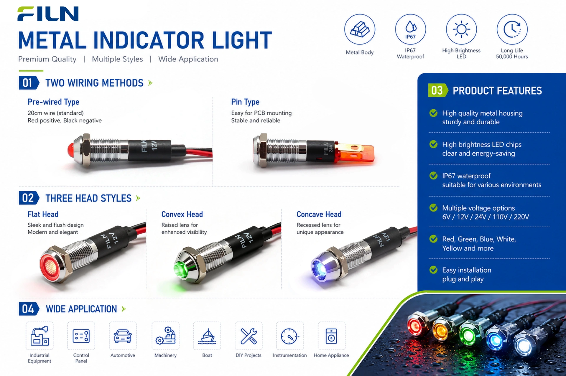
Wiring options include solder pin terminals, quick-connect tabs, and pre-wired wire lead constructions. Additionally, a metallic light indicator can feature different head profiles: flat head, prominent convex head, or recessed concave head. The concave head style keeps the illuminated lens flush or slightly recessed within the metal body, preventing accidental impact damage in high-traffic work zones.
PRODUCT OVERVIEW: FL1M-12CW-1 SIGNAL LAMP
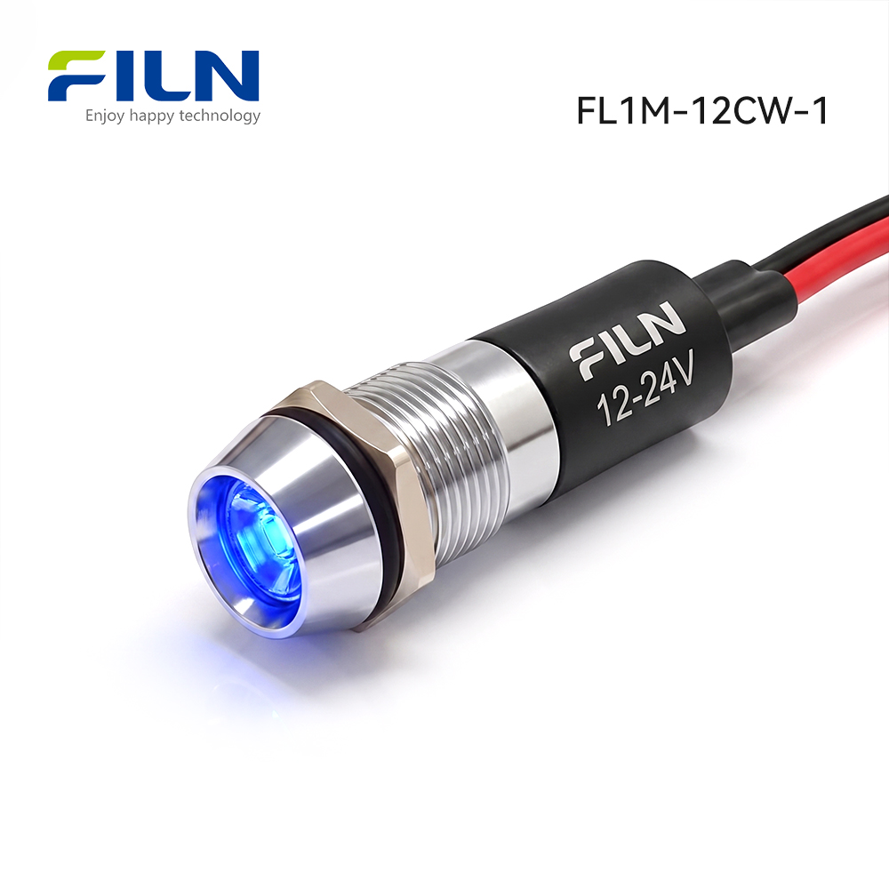
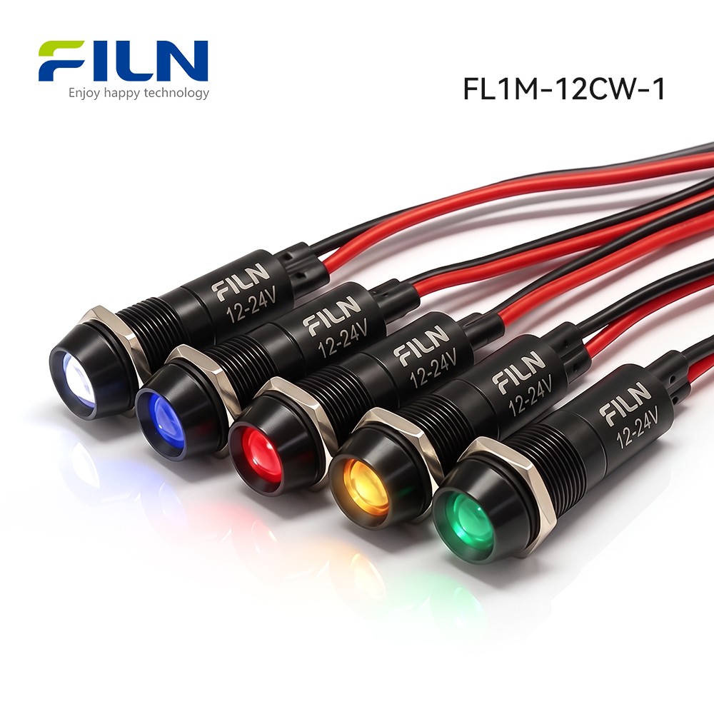
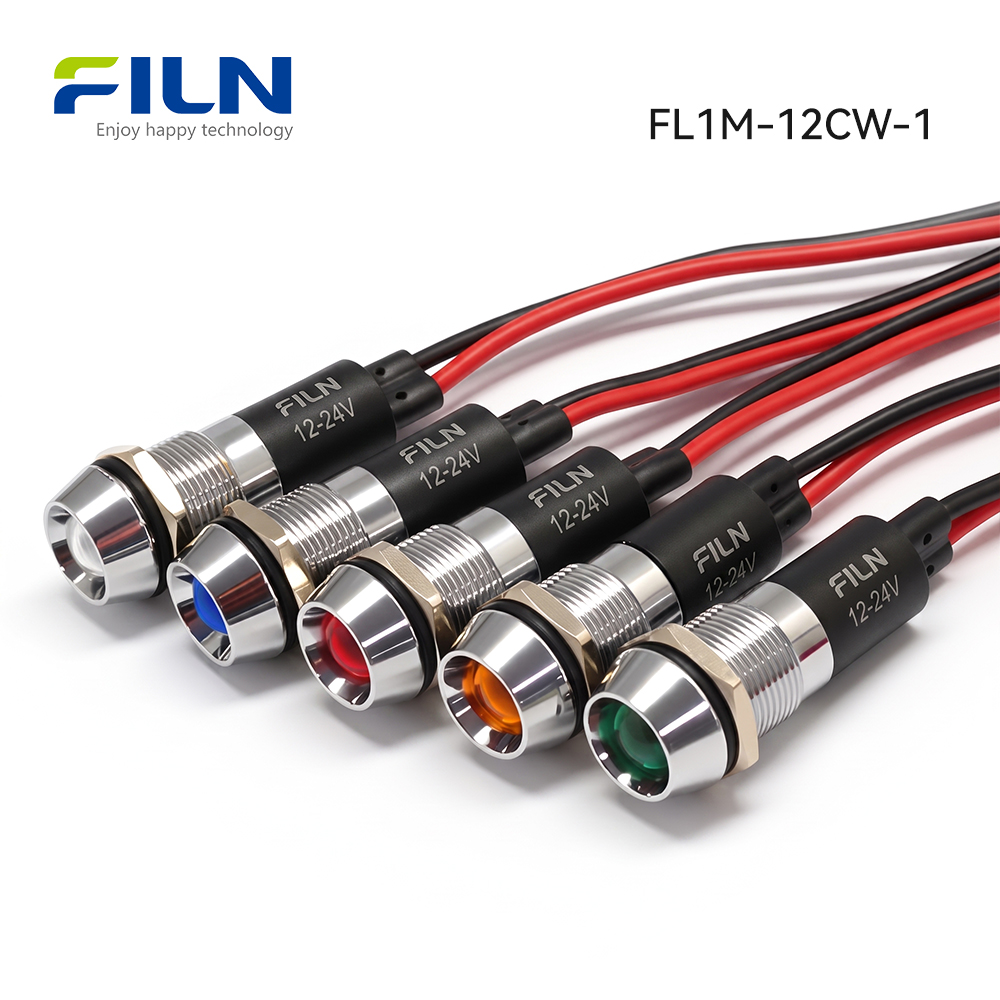
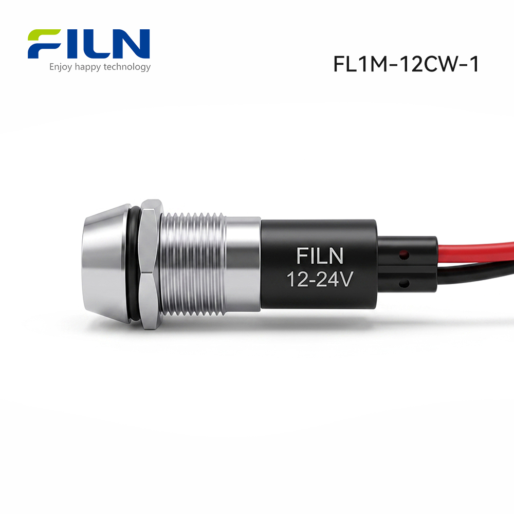
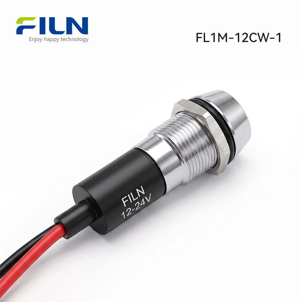
The FL1M-12CW-1 light indicator is built around a standard 12mm thread diameter, making it an ideal choice for compact operator panels and dense power distribution racks. Manufactured with a precision-machined nickel-plated brass or black zinc alloy casing, this light indicator possesses structural durability that easily outlasts plastic alternatives under mechanical vibration and chemical contact.
Electrically, each light indicator housing encloses a high-efficiency LED die matched with an internal current-limiting resistor. When energized, the recessed concave optical polycarbonate lens emits focused, vivid light. Pre-wired with flexible 2PIN wire leads, this light indicator simplifies field installation by allowing direct connection into terminal blocks without manual soldering.
Fully certified under UL (Certificate Number: E498776), CE, VDE, RoHS, CCC, and ISO9001 standards, this light indicator offers IP65 ingress protection. It is widely specified across power distribution cabinets, laboratory testing setups, energy storage systems, marine consoles, and custom automotive modifications. B2B procurement teams can purchase units directly from the factory, request custom lead lengths, or download 3D CAD models.
QUICK TECHNICAL SPECIFICATIONS
| Specification Parameter |
Technical Specification Data |
| Product Description |
Concave head metal light indicator with pre-wired lead wires |
| Model Designation |
FL1M-12CW-1 |
| Mounting Hole Cutout |
12 mm / 0.472 inches (Panel cutout) |
| Operating Voltage Options |
3V, 6V, 12V, 24V, 36V, 110V, 220V AC/DC (Customizable) |
| LED Illumination Colors |
Red, Green, Yellow, Blue, White, Bi-color, Tri-color options |
| Waterproof Protection Rating |
IP65 Sealed |
| Termination Wiring Type |
2PIN Pre-wired lead cables (200mm standard length) |
| Head Profile Design |
Concave head profile design |
| Surface Finish Standards |
Smooth metallic plating, burr-free, non-oxidizing finish |
| Assembly Components Included |
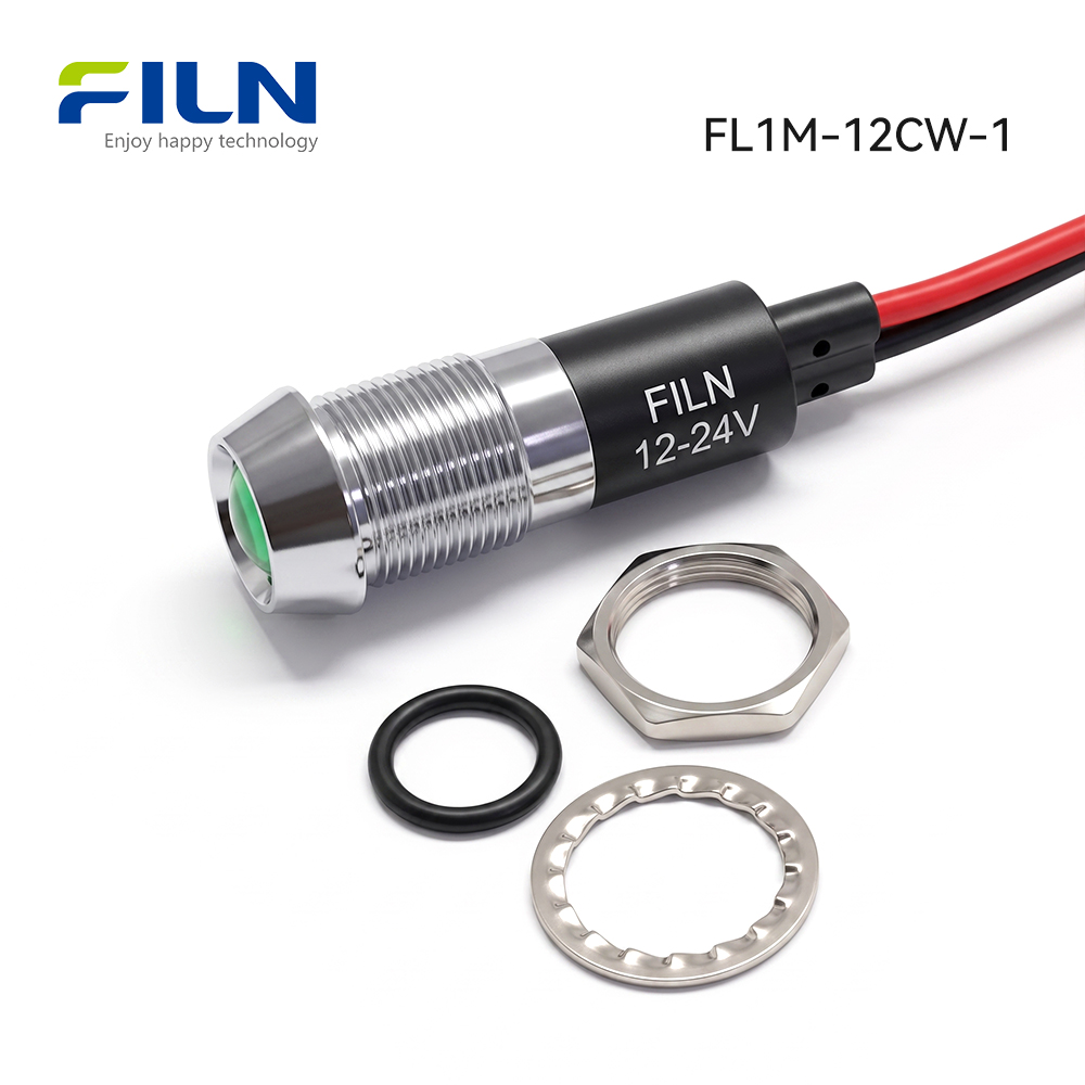
1x Light indicator, 1x Silicone waterproof seal, 1x Washer, 1x M12 Nut |
ELECTRICAL & MECHANICAL PERFORMANCE PARAMETERS
| Performance Rating Category |
Engineering Parameter Value |
| Rated Operating Voltage Range |
3V – 220V DC/AC (Custom potential ranges available from factory) |
| AC Frequency Range |
50 Hz / 60 Hz |
| Rated Operational Current |
≤ 20 mA at standard drive potential |
| Rated Power Consumption |
Approx. 0.2 Watts per light indicator unit |
| Insulation Resistance |
≥ 100 MΩ (Tested at 500V DC between conductor and metallic shell) |
| Dielectric Withstand Potential |
1500V to 1800V AC for 1 min (No breakdown or flashover) |
| Operating Lifespan Expectancy |
50,000 to 100,000 continuous operating hours |
| Waterproof Ingress Protection |
IP65 Water splash and dust ingress certified |
COMPONENT MATERIALS & ENGINEERING SELECTION
| Component Name |
Selected Material Grade |
Engineering Rationale & Advantages |
| Outer Housing Shell |
Nickel-Plated Brass / Black Zinc Alloy |
Provides structural strength, corrosion defense, and protection for internal parts. |
| Internal Base Housing |
PA66 Flame-Retardant Nylon |
Ensures electrical insulation and heat resistance inside electrical cabinets. |
| Concave Lens Diffuser |
Optical Grade Polycarbonate (PC) |
Offers high impact strength and clear light focus within a recessed head profile. |
| Luminescent Source |
High-Brightness LED Die |
Delivers bright visual output with minimal energy draw and heat generation. |
| Internal Resistor Element |
Carbon Film Resistor Assembly |
Regulates operational drive current across rated voltage parameters. |
| Termination Lead Wires |
High-Flexibility PVC Insulated Wire |
Guarantees dependable electrical conductivity and flexible routing inside panels. |
| Panel Mounting Nut |
Machined Brass / Copper Alloy |
Maintains tight thread locking to prevent loosening caused by vibration. |
| Sealing Waterproof Ring |
Silica Gel (Silicone Rubber) |
Compresses tightly against panel surfaces to establish an IP65 waterproof seal. |
| Lock Washer Gasket |
Stainless Steel Spring Gasket |
Maintains spring tension against the panel back to prevent rotational movement. |
ENVIRONMENTAL SPECIFICATIONS & TESTING STANDARDS
This engineering specification applies across the entire FILN metal concave head light indicator family. Rigorous lab testing confirms performance across thermal swings, high humidity, and harsh environments.
| Environmental Test Parameter |
Test Conditions & Engineering Pass Criteria |
| Operating & Storage Temperature |
-40°C to +80°C continuous ambient operating range |
| Operating Relative Humidity |
≤ 85% RH at +40°C non-condensing atmosphere |
| High Temperature Soak Test |
96 continuous hours at +80°C ± 2°C with zero physical degradation |
| Low Temperature Soak Test |
96 continuous hours at -40°C ± 2°C with zero casing embrittlement |
| Humidity Aging Resistance |
96 hours at +40°C ± 2°C with 90% to 95% relative humidity exposure |
| Thermal Shock Cycling Test |
5 cycles: Rapid transition between -40°C (30 min) and +85°C (30 min) |
LED OPTICAL & ELECTRO-TECHNICAL DATA
1. Absolute Maximum Ratings (Ta = 25°C)
| Electro-Optical Property |
Symbol |
Maximum Safe Limit |
| Max Forward DC Current |
IFP |
20 mA |
| Peak Reverse Protection Potential |
VR |
5 V |
| Power Dissipation Limit |
PD |
60 mW |
| Operating Ambient Range |
TOPR |
-40°C to +80°C |
| Storage Ambient Range |
TSTG |
-40°C to +100°C |
| Lead Soldering Heat Limit |
TSOL |
Max 260°C for 3 seconds |
2. Electro-Optical Characteristics (Ta = 25°C)
| Parameter Description |
Test Conditions |
Min Value |
Typ Value |
Max Value |
| Forward Voltage Drop (VF) |
IF = 20mA |
2.8 V |
3.0 V |
3.2 V |
| Reverse Leakage Current (IR) |
VR = 5V |
— |
— |
5 μA |
| Viewing Angle Dispersal (2θ½) |
IF = 20mA |
— |
45° |
— |
| Luminous Intensity Output (Iv) |
IF = 20mA |
500 mcd |
650 mcd |
800 mcd |
| Dominant Wavelength Spectrum |
IF = 20mA |
520 nm |
523 nm |
525 nm |
| Junction Temperature Limit (Tj) |
IF = 20mA |
— |
— |
125°C |
| Thermal Resistance Parameter (RJP) |
IF = 20mA |
— |
8 °C/W |
— |
STANDARD TESTING ATMOSPHERIC CONDITIONS
Unless explicitly noted otherwise in custom engineering documentation, all electro-optical parameters for this light indicator product line are measured under controlled laboratory environmental conditions:
| Environmental Test Variable |
Standard Atmospheric Range |
| Ambient Test Temperature |
5°C to 35°C |
| Relative Test Humidity |
45% to 85% RH |
| Atmospheric Barometric Pressure |
86 kPa to 106 kPa (860 mbar to 1060 mbar) |
Engineering Standard Note: Optical intensity and dominant wavelength values for each light indicator unit conform to CIE international human eye response standards. Allowed luminous intensity tolerance is ±15%, and drive potential tolerance is ±0.1V.
INDUSTRIAL APPLICATIONS & USE CASES
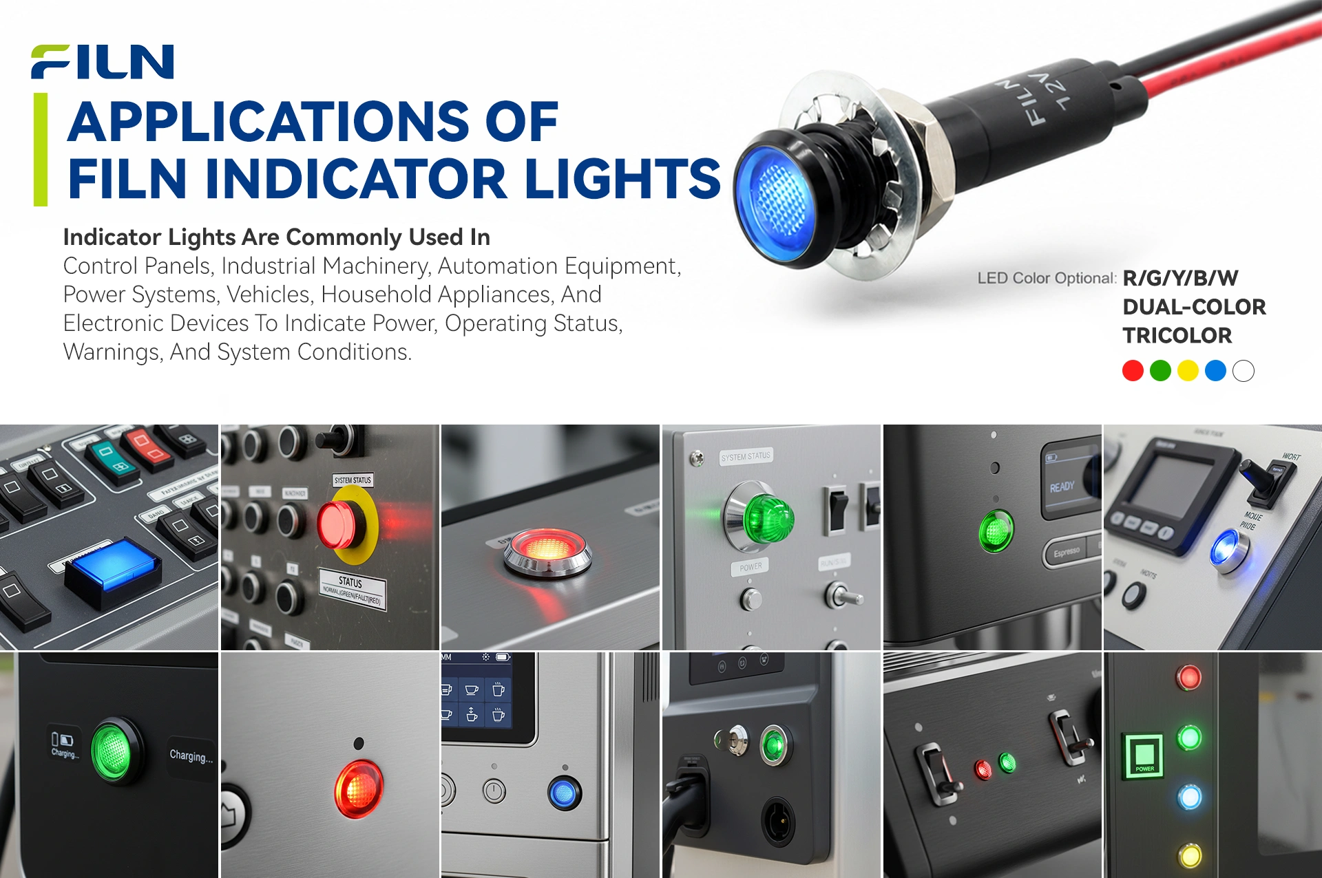
A metallic light indicator constructed with nickel-plated brass or zinc alloy delivers high impact durability and IP65 sealing. Unlike plastic indicators that degrade under mechanical stress or chemical contact, a concave head metal light indicator excels in demanding industrial scenarios:
1. Industrial Automation & Equipment Control Panels
Industrial control panels require clear status signaling that survives frequent operator contact:
- Machinery Control Interfaces: Concave head light indicator units mounted on dense control panels provide bright status signals while remaining flush enough to avoid snagging gloves or tools.
- Distribution Enclosures: Compact 12mm light indicator units provide clear power state and fault monitoring inside electrical cabinets.
- Laboratory Test Equipment: Precision instruments utilize custom voltage light indicator lamps to signal active test routines or high-voltage hazard states.
2. Renewable Energy & Outdoor Power Stations
Clean energy equipment requires weather-sealed signal lights that withstand wide temperature swings:
- EV Charging Terminals: A waterproof light indicator signals system readiness, active charging, or fault isolation under direct sunlight.
- Solar Combiner Enclosures: Weatherproof light indicator units monitor inverter output status across operating temperatures from -40°C to +80°C.
3. Marine Consoles, Boats & Custom Vehicles
Marine and automotive builds require vibration protection and salt-spray resistance:
- Yacht Control Consoles: Corrosion-resistant metal light indicator units installed behind silicone seals withstand salt spray and moisture exposure.
- Custom Vehicle Dashboards: Recessed concave head light indicator units installed on modified off-road dashes provide clean status alerts for auxiliary pumps, lights, and winches.
4. Public Access & Commercial Machinery
Vandal-resistant metal construction protects public-facing machinery:
- Self-Service Kiosks: A metal light indicator resists impact damage and tampering on public transaction equipment.
- Commercial Food Equipment: IP65-sealed light indicator lamps endure daily cleaning cycles and thermal exposure without seal failure.
INDICATOR LIGHT COLOR CODES & FUNCTIONAL MEANINGS
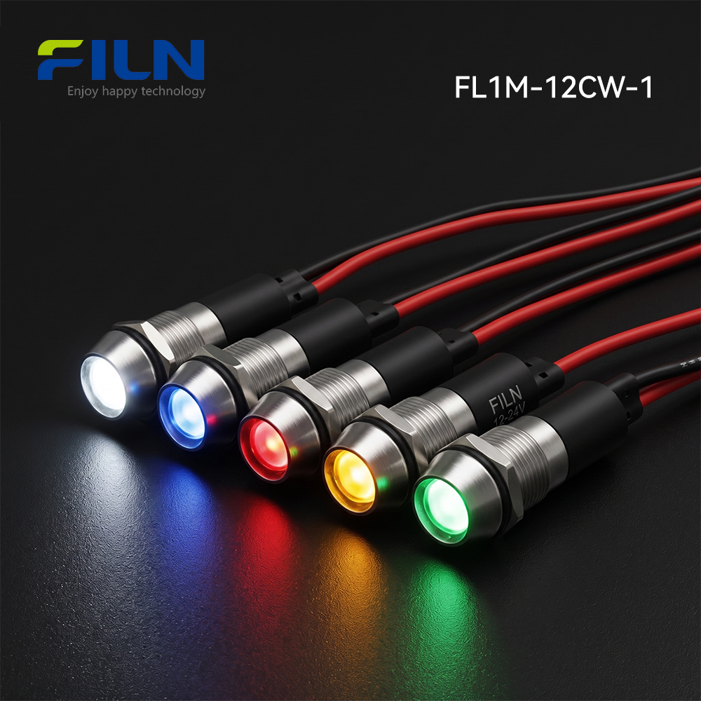
Standard industrial human-machine interfaces rely on color-coded signals so operators can assess machinery health at a glance. FILN produces light indicator models in five single primary colors, as well as multi-color bi-color and tri-color configurations:
| Color |
Standard Functional Meaning |
Typical Application Scenario |
Engineering Rationale |
| Red (R) |
Danger, Fault, Emergency Stop |
Critical overload fault, over-temperature alarm, safety trip |
Demands immediate operator attention; universally signals emergency stop or danger. |
| Green (G) |
Normal Operation, Ready, Safe |
Motor running, system operational, normal pressure confirmed |
Confirms normal operating parameters without active faults. |
| Yellow (Y) |
Caution, Standby, Monitoring |
Thermal limit warning, scheduled maintenance due |
Alerts operators to monitor conditions before a system fault develops. |
| Blue (B) |
Mandatory Action, Specific State |
Manual reset required, data link active |
Designated for specific operator actions outside standard safety warnings. |
| White (W) |
General Power On, Neutral Status |
Main breaker energized, baseline power active |
Provides clear power-on indication without implying safety or alarm states. |
FILN bi-color and tri-color light indicator units house multiple LED dies inside a single 12mm metal body, allowing dynamic multi-state status signaling within a single panel cutout.
STEP-BY-STEP PANEL INSTALLATION GUIDE
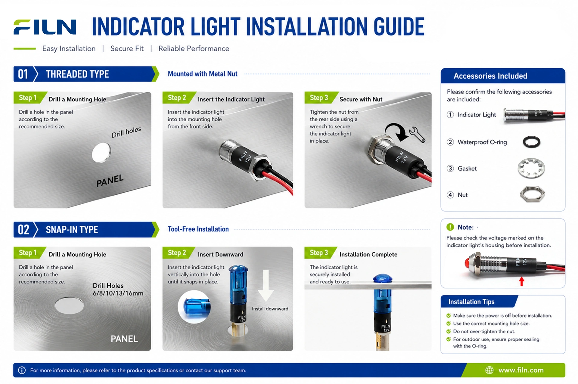
Follow this step-by-step installation process to securely mount your light indicator and maintain an IP65 waterproof seal against the panel face:
- Panel Cutout Preparation: Punch or drill a clean 12.0mm circular mounting hole through your enclosure panel. Remove burrs and clean the surrounding surface.
- Waterproof Gasket Placement: Slide the silicone waterproof O-ring over the rear wire leads of the light indicator until it rests flush against the front metal bezel.
- Front Panel Insertion: Insert the wire leads and threaded shank through the front of the panel cutout until the silicone seal presses flat against the panel face.
- Rear Lock Assembly: From behind the panel, pass the stainless steel lock washer over the wires, followed by the brass M12 locknut.
- Torque FastENING: Thread the M12 nut onto the housing, then tighten with a wrench to 1.5–2.0 Nm torque to compress the silicone gasket evenly.
- Electrical Lead Connection: Connect the 2PIN pre-wired leads into your power circuit using terminal blocks, quick-connect connectors, or soldered inline splices.
TERMINATION STYLE COMPARISON & SAFETY PROCEDURES
Choosing the correct termination style for a light indicator depends on enclosure depth, installation speed requirements, and environmental vibration levels:
| Terminal Style |
Pros / Key Advantages |
Cons / Limitations |
Recommended Application Scope |
| Pre-Wired Lead (FL1M-12CW-1) |
Fast wiring via lever connectors, wire nuts, or terminal blocks; excellent moisture sealing inside the metal shell. |
Fixed factory cable length (custom lengths must be requested when ordering). |
High-vibration machinery, outdoor control boxes, wet processing plants. |
| Solder Pin Terminal (FL1M-12CJ-1) |
Shallow rear profile depth; supports direct wire soldering or plug-in PCB connections. |
Requires manual soldering during panel assembly; exposed terminals need heat-shrink insulation. |
Compact control boxes, shallow enclosures, low-vibration instruments. |
To order solder pin terminal models, visit our 12MM Pin Terminal Flat Head Indicator Light FL1M-12CJ-1 Product Page.
Electrical Safety Warning: Always disconnect main power feeds before performing electrical wiring. When connecting pre-wired light indicator leads, use lever connectors or crimp terminals with heat-shrink tubing to ensure solid conductivity and prevent electrical shorts.
INDUSTRY KNOWLEDGE BASE & TROUBLESHOOTING
Preventing Phantom Illumination (Faint Glowing)
Phantom illumination occurs when a light indicator glows faintly even when switched off. This is caused by leakage currents passing through solid-state relays, capacitive coupling along long parallel wire runs, or PLC leakage outputs. Because efficient LED light indicator components draw very little current, micro-amp leakage levels can produce faint luminescence.
Engineering Solution: Connect a low-wattage bleed resistor or RC snubber circuit in parallel across the light indicator wire leads to divert stray leakage current away from the internal LED assembly.
Common Troubleshooting Procedures
- Indicator Fails to Illuminate: Verify wire lead polarity on DC power lines (red lead positive, black lead negative). Ensure supply line potential matches the rated rating of your light indicator unit.
- LED Burnout Upon Power-On: Occurs when high line potential (e.g., 110V/220V) is applied to a low-voltage light indicator without an internal drop resistor. Verify input potential before powering up circuits.
- Moisture Ingress Behind Panel: Check that the silicone washer rests flat against the panel face and that the rear M12 nut is torqued correctly.
B2B BUYER DECISION & SELECTION GUIDE
When specifying light indicator products for large-scale manufacturing or commercial projects, keep these core selection parameters in mind:
- Panel Hole Size: Match cutout parameters. Popular sizes include 6mm, 8mm, 10mm, 12mm, 16mm, 22mm, and 30mm.
- System Voltage Selection: Match system requirements (3V–220V) to eliminate the need for external drop resistors.
- Ingress Protection: Require IP65 or higher sealing for washdown, outdoor, or marine environments.
- Safety Certifications: Require UL, CE, and RoHS approvals to streamline international compliance.
Recommended Similar Light Indicator Products
WHY OEM ENGINEERS & PROCUREMENT DIRECTORS CHOOSE FILN
Procurement teams and design engineers partner with FILN for direct factory support and flexible customization:
| Factory Direct Advantage |
Direct factory purchasing eliminates distributor markups, ensuring competitive wholesale pricing for every light indicator order. |
| Zero Minimum Order Quantity |
No MOQ requirements mean engineers can order small sample lots for prototyping before committing to full production runs. |
| Rapid Prototyping Delivery |
Sample light indicator orders ship within 24–72 hours, while volume orders finish production within 7 business days. |
| Full OEM / ODM Customization |
Custom cable lengths, special wire jacketing, pre-crimped terminal plugs, custom drop resistors, and laser etching. |
| In-House Testing Laboratory |
Every lot of light indicator units undergoes strict testing for insulation resistance, dielectric strength, waterproofing, and luminous decay. |
FACTORY DIRECT MANUFACTURING & GLOBAL SUPPLY CAPACITY
Yueqing Yulin Electronic Co., Ltd., trading internationally under the FILN brand, was established in 2006 in Wenzhou, Zhejiang, as an electrical switch manufacturer integrating R&D, manufacturing, and direct sales. Today, FILN light indicator models and indicator switch components are exported to over 100 countries worldwide. Operating a modern 10,000 m² factory with 20+ automated production lines and an independent testing lab, FILN operates under strict ISO9001 quality standards.
FILN certified product lines (UL, CE, VDE, RoHS, REACH, TUV, CB) are widely specified across kitchen appliances, energy storage systems, EV charging networks, automotive modifications, marine consoles, and industrial equipment.
| Core Manufacturing Line |
Metal light indicator units, pushbutton switches, rocker switches, toggle switches, custom wire harness sub-assemblies. |
| Quality System & Approvals |
ISO9001, CE, VDE, RoHS, SGS, UL (Certificate Number: E498776), IP65, TUV certified. |
| Global Export Reach |
United States, Canada, Germany, United Kingdom, Australia, and over 100 countries worldwide. |
| Official Web Portal |
www.filn.com |
| Direct Engineering Contact Email |
inquiry@cnylin.com.cn |
FREQUENTLY ASKED QUESTIONS (FAQ)
1. How to eliminate phantom glowing in a LED light indicator circuit?
Phantom illumination in a light indicator circuit is caused by residual leakage currents passing through solid-state relays or parallel wiring induction. Installing a bleed resistor or RC snubber across the wire leads diverts this stray leakage safely away from the LED.
2. Can this IP65 light indicator withstand direct liquid washdowns?
Yes. The nickel-plated brass or black zinc alloy casing, polycarbonate lens, and silicone seal on this light indicator endure direct water spray and routine chemical washdowns on processing equipment.
3. What is the official UL certificate number for this light indicator product line?
The FILN metal light indicator family is certified under UL Certificate Number E498776, verifying compliance with international safety standards.
4. What mounting hole cutout size is required for model FL1M-12CW-1?
Model FL1M-12CW-1 requires a standard 12mm (0.472 inch) circular panel cutout for installation.
5. Does this light indicator require an external resistor for 220V operation?
No. High-voltage models contain built-in carbon film current-limiting resistors, allowing direct connection across 110V or 220V AC lines.
6. What standard lead wire length is supplied on this light indicator model?
Standard stock units feature 200mm (8 inches) of flexible 2PIN pre-wired PVC leads. Custom cable lengths can be ordered directly from our factory.
7. Why select a concave head light indicator over a prominent head model?
A concave head light indicator keeps the optical lens recessed inside the metal bezel, preventing impact damage from passing equipment or operator tools in tight workspaces.
8. Can FILN supply customized wire lengths and terminal plugs?
Yes. As a direct manufacturer, FILN offers custom lead lengths, specialized wire jackets, and pre-crimped quick-connect terminals.
9. What visual color options are available for this light indicator product?
FILN manufactures red, green, yellow, blue, and white single-color units, as well as bi-color and tri-color LED configurations.
10. What is the operational lifespan of this metal light indicator?
The embedded LED light source is rated for 50,000 to 100,000 hours of continuous operation under rated electrical conditions.
11. What lens shape options are available for 12mm metal indicators?
FILN manufactures concave head, flat head, and prominent convex head metal indicators to match diverse visual and physical panel requirements.
12. Is there a minimum order quantity (MOQ) for custom engineering samples?
No. FILN maintains a zero minimum order quantity policy (No MOQ) for standard stock and custom sample orders to support design engineering work.
13. What sealing component provides the IP65 waterproof barrier?
A flexible silicone O-ring gasket fits between the metal bezel flange and the panel face, forming a waterproof seal when the rear nut is tightened.
14. What is the rated operating temperature range for this light indicator model?
This light indicator operates reliably across ambient environmental temperatures ranging from -40°C to +80°C.
15. What torque level should be applied when tightening the rear M12 nut?
We recommend applying 1.5 Nm to 2.0 Nm torque to secure the M12 hex nut against the panel back without damaging internal threads or the silicone seal.
16. Are 3D STEP files and CAD models available for engineering designs?
Yes. STEP models, 3D CAD files, and technical drawing schematics are available upon request from our engineering support team.
17. How do pre-wired wire lead light indicator models accelerate assembly?
Pre-wired leads eliminate hand-soldering terminals inside control panels, speeding up production and eliminating potential cold solder joint defects.
18. What quality management systems govern FILN light indicator production?
FILN plants operate under ISO9001 quality systems, ensuring lot traceability, automated inspection, and batch testing.
19. Can DC version light indicator units work directly on AC power lines?
Standard DC units require polarity-correct direct current. However, FILN supplies universal AC/DC light indicator units upon request.
20. How can industrial procurement buyers order wholesale light indicator units?
Procurement teams can request direct factory price quotes, commercial terms, and custom production runs by emailing inquiry@cnylin.com.cn.