Key Takeaways
- Heavy-Duty Hardness: Precision-machined copper or zinc alloy shell outperforms fragile plastic alternatives under heavy mechanical impact.
- High-Visibility Point Lighting: Features a flush head lens with an explicit center-point light effect for crisp status communication on dense console boards.
- Integrated Wire Harness: Outfitted with 2PIN dual 20cm wires (40cm cumulative length) to eliminate post-mount field terminal soldering.
- Compact 8mm Cutout: Maximizes available surface space for panel builders while providing intense localized illumination.
- IP65 Ingress Security: Sealed with an industrial silicone ring to isolate internal electronics from oils, humidity, and fine dust.
- Full Global Credentials: Fully compliant with CE, VDE, RoHS, ISO9001, and CCC guidelines, ensuring rapid compliance approval for industrial exports.
- Extended Operational Life: Solid-state internal LED semiconductor elements maintain peak luminosity for up to 100,000 continuous hours.
- Custom Voltage Integration: Manufactured natively for 3V to 220V AC/DC configurations, matching specialized power system designs.
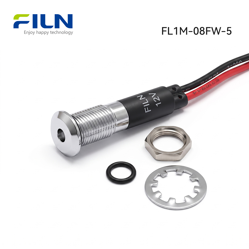
- Complete Installation Kit: Ships as a unified system including 1x Indicator Light, 1x Waterproof Ring, 1x Tension Washer, and 1x M6 Hex Nut.
What is an Equipment Panel Indicator?
An equipment panel indicator is a highly ruggedized, panel-mounted optoelectronic status lamp engineered to give machine operators clear, real-time visual feedback regarding circuit power, automated cycles, and system faults. By housing a highly efficient solid-state light-emitting diode and matching internal carbon film resistor within a durable metal body, this signaling device reliably tracks system conditions across heavy distribution networks and automated lines.
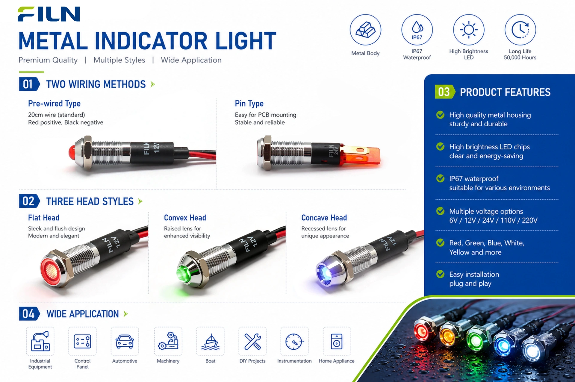
As an established, direct-supply indicator light factory, FILN provides an extensive range of signaling selections to meet various mechanical layouts. Our product lines feature high-grade metal indicator light bodies and economical plastic indicator configurations, with mounting diameters available from 6mm up to 30mm. To accommodate different wiring preferences, panel builders can choose between standard solder pin terminals or integrated, flexible insulated wire leads. The premium metal housings are manufactured in flat head, elevated convex head, and recessed concave head shapes, allowing engineering teams to balance aesthetic preferences with field visibility requirements.
Product Overview & Operational Analysis
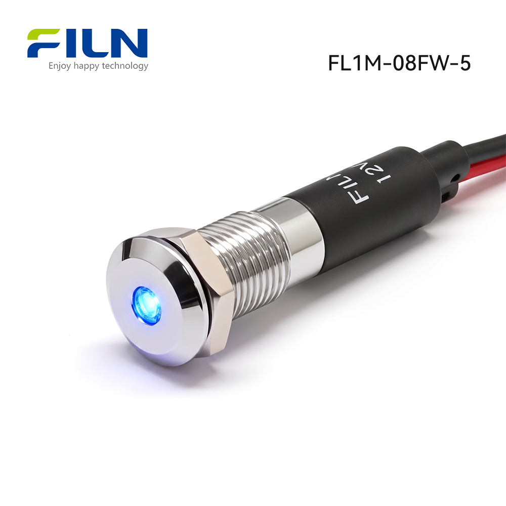
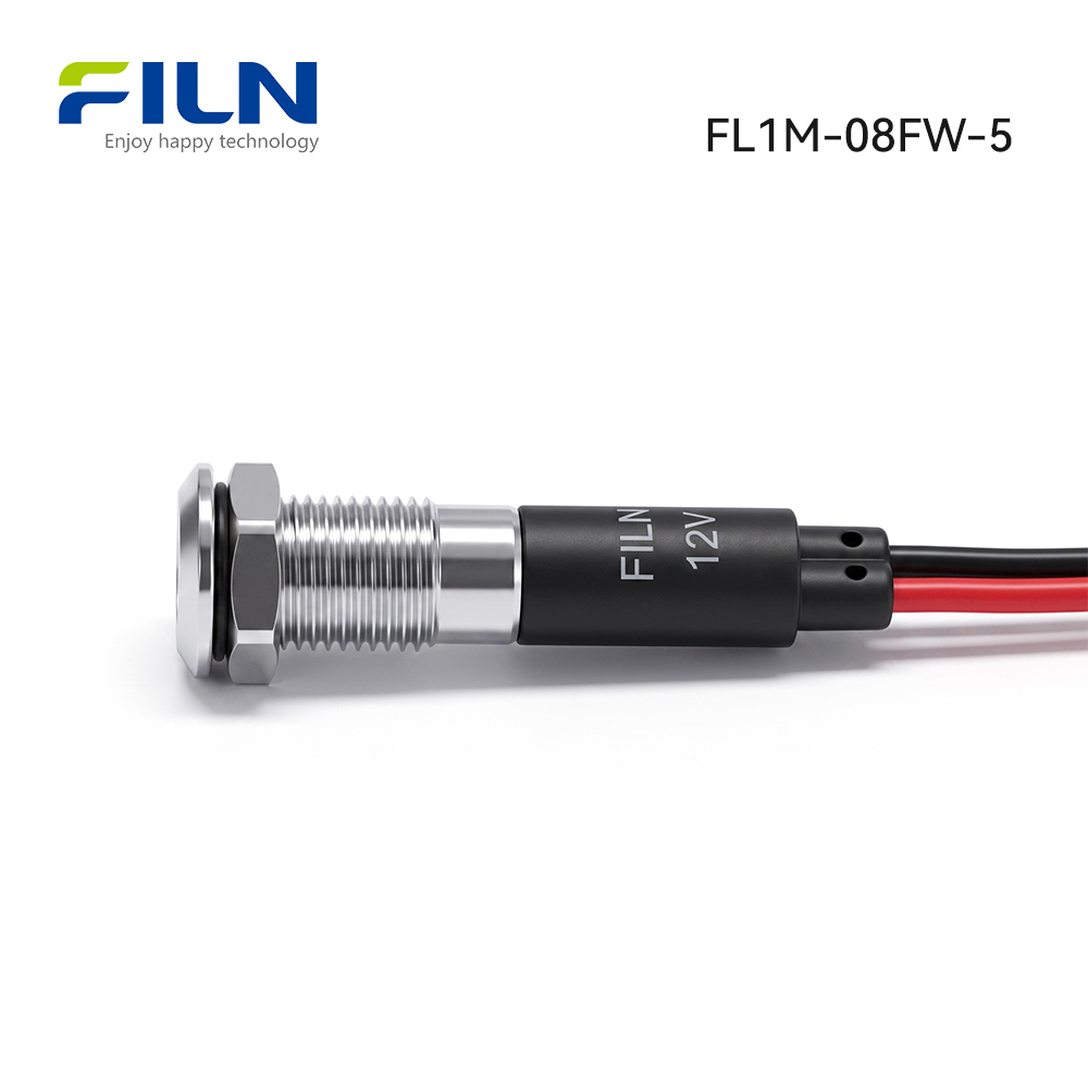
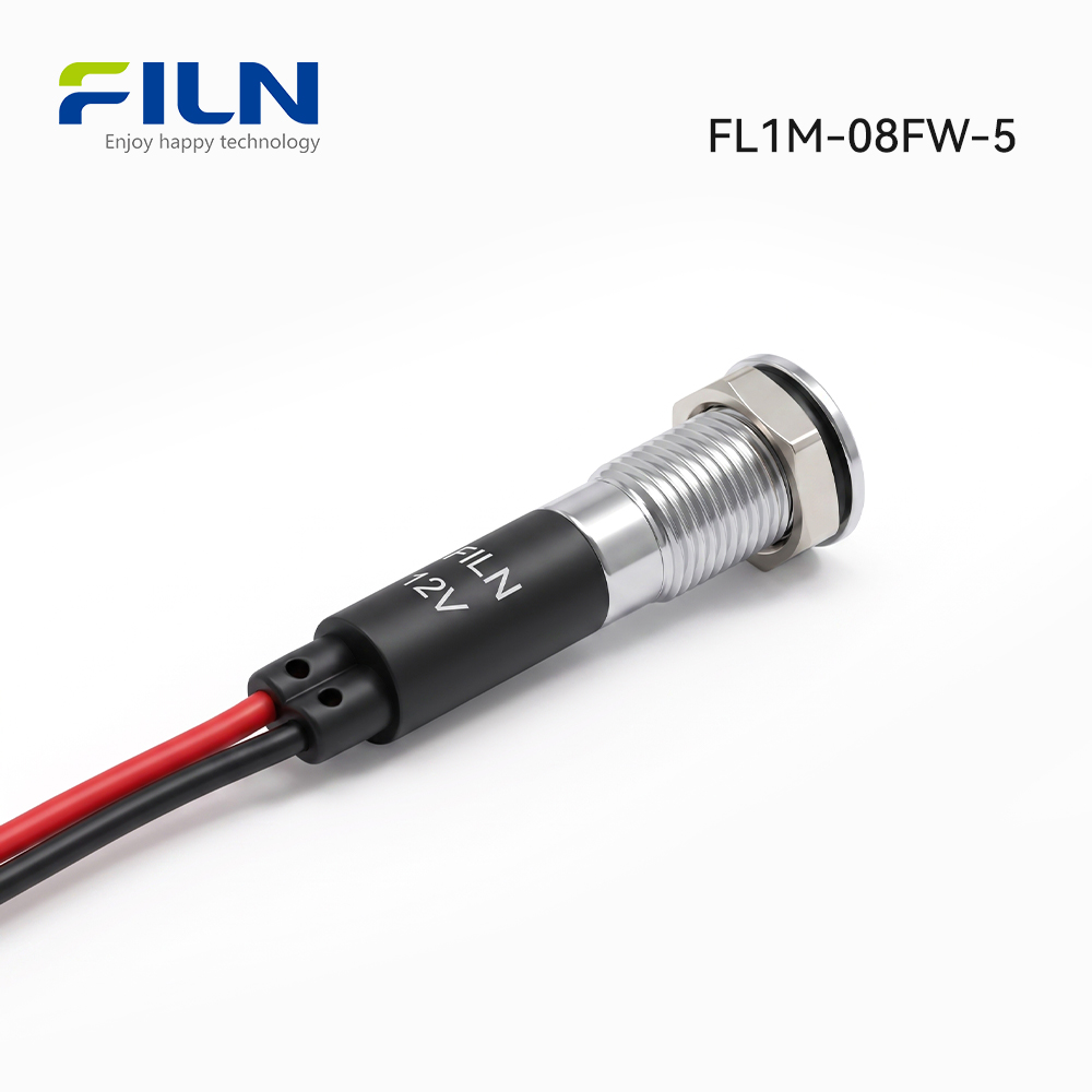
The FILN FL1M-08FW-5 series equipment panel indicator uses a streamlined flat face profile with a distinct center point-lit effect to provide a crisp, modern visual indicator on crowded control boards. Its internal mechanical design features a fine-threaded metal barrel held firmly by a solid hex nut, keeping the unit perfectly aligned and preventing rotation even under severe mechanical vibration. This integrated wire lead configuration provides a reliable electrical connection by removing external terminal junctions behind the mounting surface.
Electrically, the device houses a high-luminescence semiconductor chip connected to an internal current-limiting carbon film resistor. This internal network allows safe operation across tailored voltages from 3V up to 220V AC or DC, maintaining current consumption below 20mA. The durable alloy body provides strong dielectric protection, fully insulating the current-carrying components from the metal enclosure wall to ensure safe, stable operation.
Because the dual wire leads are molded directly into the base assembly, this equipment panel indicator is highly resistant to wire strain and corrosion. It is widely used in power distribution networks, renewable energy systems, laboratory test setups, and heavy automation consoles. Backed by valid CE, VDE, RoHS, ISO9001, and CCC certifications, the unit utilizes premium PA66 nylon bases and impact-resistant polycarbonate lenses to deliver dependable, long-term performance in demanding industrial facilities.
Quick Specifications
The structural measurements and configuration variables below provide the technical guidelines needed to integrate the FL1M-08FW-5 component into new or existing control panels.
| Specification Parameter |
Technical Data Value |
| Description |
Metal indicator light with wire leads |
| Model Reference |
FL1M-08FW-5 |
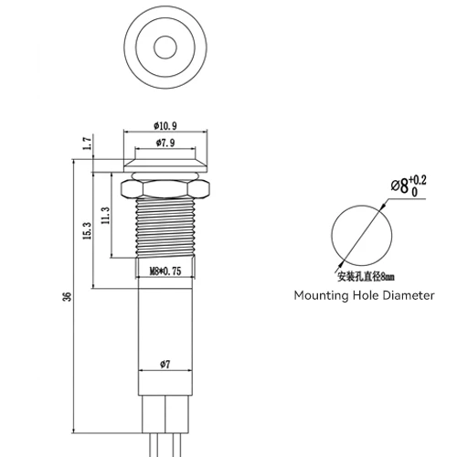
| Mounting Hole Cutout Size |
8mm (0.315 Inches) |
| Operating Voltage Baseline |
3V to 220V AC/DC Flexible Options (Fully Customizable) |
| Available LED Luminous Output |
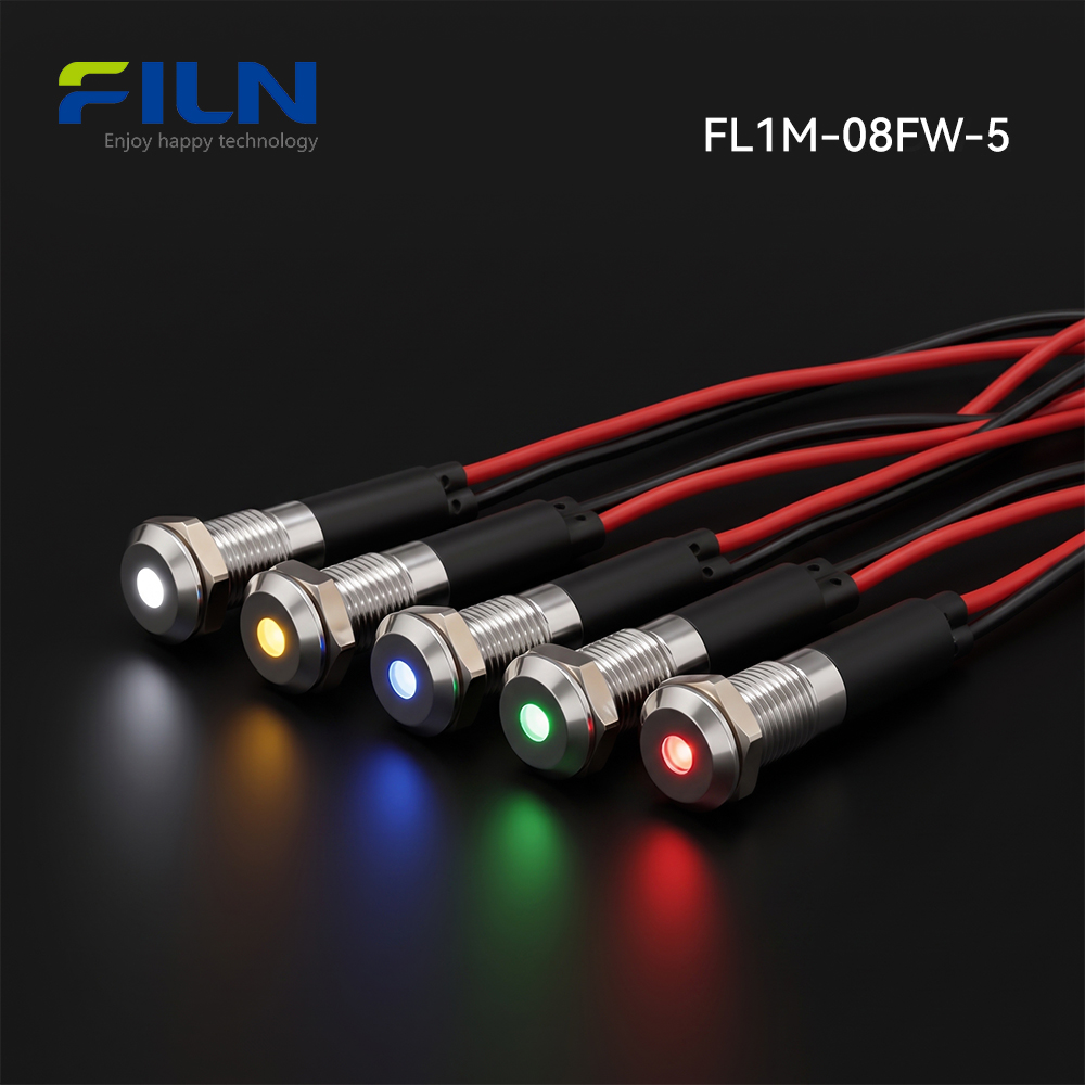
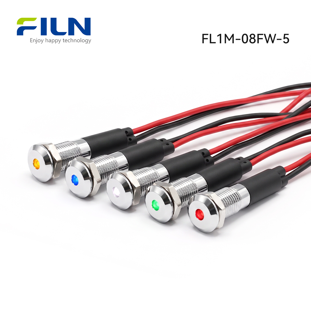
Red (R) / Green (G) / Yellow (Y) / Blue (B) / White (W) |
| Ingress Moisture Rating |
IP65 Waterproof Level with included seating gasket |
| Wiring Scheme & Dimensions |
Dual 20cm pre-wired pigtails, 40cm cumulative loop, 2PIN direct feed |
| Face Profile Type |
Flush Flat Head with Center Point Light |
| Surface Finish Matrix |
Smooth finish, free of burrs, tool score lines, oxidation, or micro-fractures |
| Mechanical Assembly Fit |
Secure interlocking barrel-to-base molding; zero component slippage, deflection, or loose fittings |
B2B Sourcing Notice: Procurement teams can request complete certified dimensional datasheets or custom wire color options by contacting our factory engineering group.
Performance Parameters
The detailed electrical ratings and mechanical thresholds below define the operating limits for the FL1M-08FW-5 point signal light under standard factory conditions.
| Performance Parameter |
Value / Measurement Metric |
| Rated Working Voltage |
3V to 220V DC / AC (Customizable to exact application limits) |
| AC Line Frequency |
50 Hz to 60 Hz |
| Rated Drive Current |
≤ 20 mA |
| Power Dissipation Metric |
Approximately 0.2 W |
| Insulation Resistance |
≤ 100 MΩ (Measured using 500V DC between internal conductors and housing shell) |
| Dielectric Strength |
1500V to 1800V AC; zero voltage breakdown, arc tracking, or degradation |
| Operational Working Life |
50,000 Hours to 100,000 Hours continuous service |
| Ingress Waterproof Shield |
IP65 Rated (Protects against direct water spray and environmental dust) |
Component Materials & Mechanical Bill of Materials
Selecting high-grade alloys and polymers protects the internal signaling components from premature failure caused by environmental stress, vibration fatigue, and structural loading.
| Component Accessory Name |
Material Composition |
Industrial Engineering Justification |
| External Housing Shell |
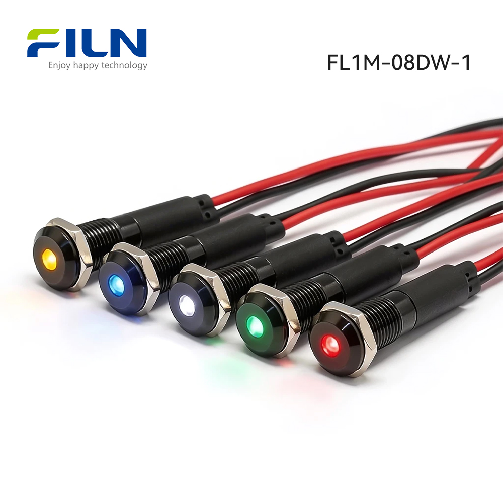
Copper Alloy / Zinc-Aluminum Alloy (Optional Black finish) |
Provides structural hardness to resist physical impact, and prevents surface corrosion from common industrial solvents. |
| Internal Lamp Holder |
Polyamide 66 (PA66 Engineered Nylon) |
Provides excellent mechanical insulation alongside exceptional resistance to high-temperature deformation. |
| Optical Lens Shield |
Polycarbonate (PC) |
Ensures clear light transmission while providing high impact resistance to prevent shattering. |
| Luminescent Source |
High-Luminosity Point LED Matrix |
Delivers sharp, high-contrast point light output with minimal power consumption. |
| Internal Resistor Unit |
Carbon Film Resistance Block |
Maintains long-term resistance value stability to protect the LED chip from electrical surges. |
| Pigtail Conductor Line |
Polyvinyl Chloride (PVC) Insulated Copper Core |
Provides flexible routing within tight cable trunks while maintaining reliable dielectric insulation. |
| Hexagonal Fastening Nut |
Machined Copper Alloy (Nickel/Chrome Finish) |
Resists thread stripping and maintains strong clamping force on the rear panel face under continuous vibration. |
| Waterproof O-Ring Seal |
High-Purity Silicone Rubber (Silica Gel) |
Forms an airtight front panel seal that resists environmental ozone, moisture, and temperature fluctuations. |
| Locking Tension Gasket |
Austenitic Stainless Steel |
Bites firmly into the rear panel surface to prevent the indicator assembly from turning or backing off. |
Environmental Durability & Stress Testing Benchmarks
The rigorous testing data below outlines the operating boundaries for our metal point-lit indicator lights across demanding field environments.
| Environmental Stress Test Category |
Applied Testing Protocol & Parameters |
| General Field Intent Baseline |
Standardized operating boundaries for general-use high-durability Metal Indicator Light series assemblies. |
| Part Classification Nomenclature |
Rugged Flush Head Point-Lit Indicator Module |
| Operating & Storage Temperature |
Operational limits span from -40°C up to +80°C |
| Operating Relative Humidity Envelope |
Maintains structural and electrical integrity at ≤85% relative humidity measured at +40°C. |
| High Temperature Endurance Profile |
Withstands continuous exposure for 96 hours at 80±2°C with zero lens distortion or insulation failure. |
| Low Temperature Cryogenic Trial |
Withstands continuous exposure for 96 hours at -40±2°C with zero wire jacket cracking or embrittlement. |
| Constant Temperature & Humidity Test |
Evaluated for 96 hours at 40±2°C with relative humidity controlled between 90% and 95% RH. |
| Thermal Temperature Cycling Profile |
Alternates between -40°C (30 min) and +85°C (30 min) for 5 complete cycles; zero seal failure. |
LED Die Semiconductor Technical Specifications
1. Absolute Maximum Ratings
These semiconductor thresholds define the safe operating boundaries for the internal point-lit LED chip to prevent permanent damage or early field failure.
| Electrical/Thermal Boundary Condition |
Absolute Maximum Limit Value |
| Maximum Peak Forward Current (IFP) |
20 mA |
| Maximum Allowable Reverse Voltage (VR) |
5 V |
| Total Safe Power Dissipation Profile (PD) |
60 mW |
| Safe Operating Temperature Envelope (TOPR) |
-40°C to +80°C |
| Long-Term Storage Temperature Range (TSTG) |
-40°C to +100°C |
| Lead-Free Reflow/Solder Heat Threshold (TSOL) |
Maximum 260°C strictly maintained for a duration under 3 seconds |
2. Electro-Optical Performance Characteristics
The electro-optical properties below define the expected luminous output and operational behaviors verified at an ambient baseline temperature of Ta=25°C.
| Electro-Optical Parameter Evaluated |
Testing Verification Conditions |
Performance Target Ranges |
| Diode Forward Voltage (VF) |
Evaluated at IF = 20mA |
Minimum: 2.8V | Maximum: 3.2V |
| Leakage Reverse Current (IR) |
Evaluated at VR = 5V |
Maximum Upper Ceiling: 5 μA |
| Luminous Spatial Viewing Angle (2θ½) |
Evaluated at IF = 20mA |
Typical Value Target: 60° |
| Luminous Intensity Output Range |
Evaluated at IF = 20mA |
Minimum: 500 mcd | Maximum: 800 mcd |
| Recommended Driving Current (IF) |
Continuous Duty Profile |
Typical Constant Value: 20 mA |
| Dominant Spectrum Wavelength (λd) |
Evaluated at IF = 20mA |
Spectral Interval: 520 nm to 525 nm |
| Maximum Internal Junction Temp (Tj) |
Evaluated at IF = 20mA |
Upper Limit: 125°C |
| Semiconductor Thermal Resistance (RJP) |
Evaluated at IF = 20mA |
Typical Characterization: 8°C/W |
Standardized Testing Conditions & Calibration Baselines
Unless explicitly noted otherwise via specialized manufacturing addendums, all electrical, physical, and optoelectronic performance figures listed are validated under the following environmental baseline parameters:
| Environmental Baseline Parameter |
Standard Baseline Testing Range Required |
| Ambient Air Testing Temperature |
Controlled between 5°C and 35°C |
| Relative Atmospheric Humidity Level |
Controlled between 45% and 85% RH |
| Barometric Air Pressure Tracking |
86 kPa to 106 kPa (Equivalent to 860 mbar to 1060 mbar) |
Technical Reference Notes: Luminous intensity outputs along with dominant spectral color coordinates are completely calibrated and verified in accordance with the official CIE international standard eye response curve. The integrated testing equipment introduces an absolute tolerance of ±15% regarding luminous intensity measurements, and a precise tolerance of ±0.1V regarding forward voltage measurement parameters.
Cross-Industry Applications & Industrial Deployment Scenarios
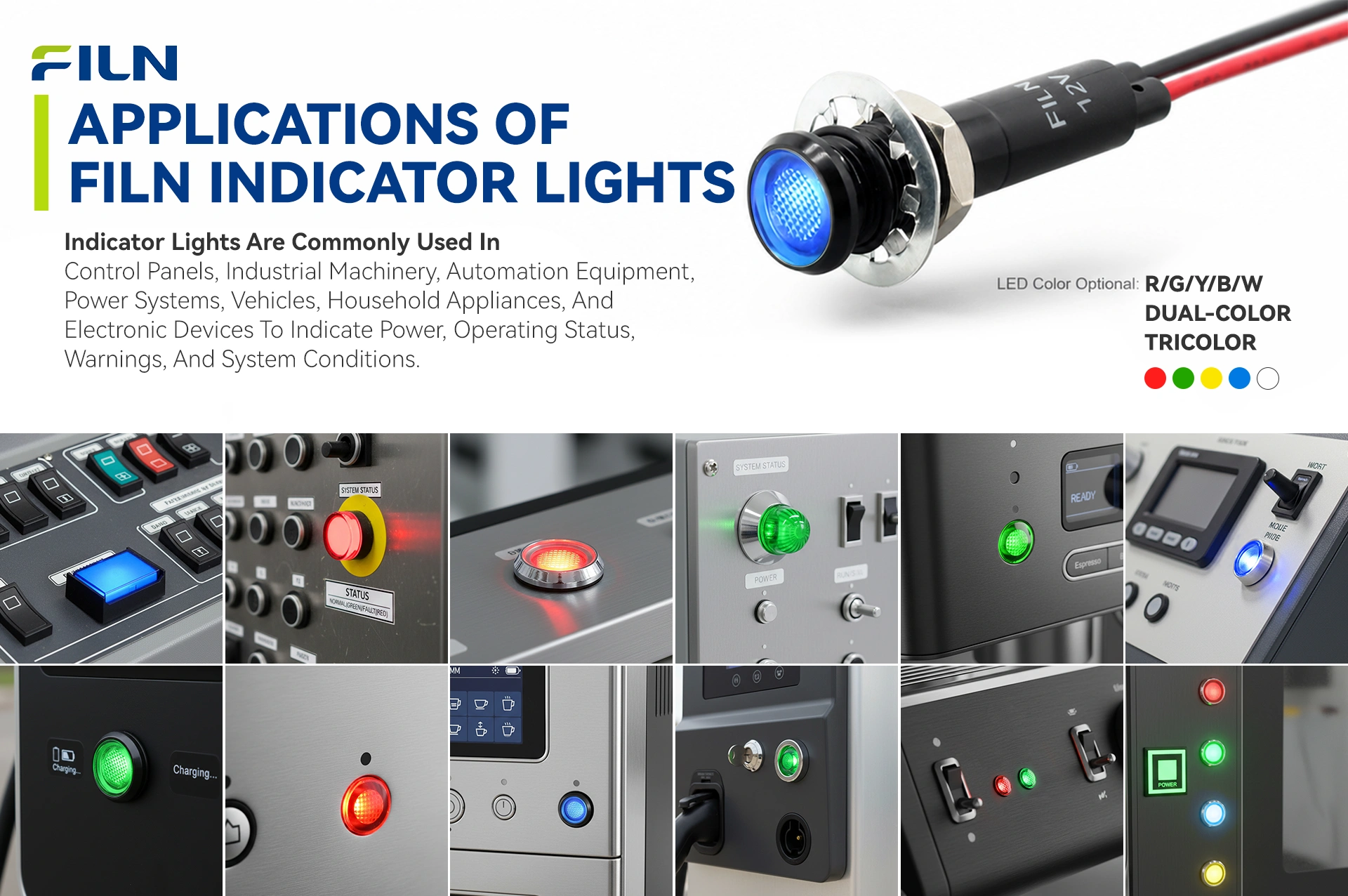
Featuring high-strength copper alloy or stainless steel bodies, FILN metal indicators provide exceptional impact resistance and IP65 dust and water protection. Standard plastic pilot lamps often crack, discolor, or deform under high operating temperatures or mechanical stress. These heavy-duty metal indicators are engineered to withstand continuous mechanical vibration and frequent washdowns across critical infrastructure and commercial setups.
I. Industrial Automation & Machinery Manufacturing
Automated shop floors expose components to continuous mechanical shocks, cutting fluids, and physical impacts. On CNC machines and processing centers, multi-color metal pilot lamps show operational status (green for active cycle execution, yellow for standby mode, and red for active errors). Their durable metal bodies prevent corrosion from cooling lubricants and flying metal shavings. For large PLC cabinets, the 8mm flush indicator provides space-saving, reliable status tracking that handles heavy equipment vibrations without coming loose.
II. Outdoor Electrical Enclosures & Renewable Energy Systems
Outdoor grid installations face severe weather exposure, wide temperature swings, and UV rays that can degrade standard non-metallic indicators. Outdoor DC/AC EV charging kiosks use these point-lit indicators to display charging states (flashing blue or green for active power flow, solid green for a complete cycle, and flashing red for ground faults). Their IP65 sealing and solid construction protect against vandalism in public areas, while maintaining dependable performance from -40°C to +80°C.
III. Rail Transit, Heavy Engineering Vehicles & Marine Gear
Mobile heavy machinery creates continuous mechanical shocks, while marine infrastructure introduces salt spray corrosion risks. Operators rely on metal panel lamps installed in heavy excavator, crane, and bulldozer dashboards to monitor critical fluid indicators like oil pressure, engine temperature, and braking status. Marine control bridges and deck-mounted hardware utilize chromium or nickel-plated bodies fitted with tight silicone O-rings to prevent saltwater ingress and resist salt-fog corrosion.
IV. Commercial Self-Service Terminals & Vandal-Prone Public Facilities
Unsupervised public terminals require robust components to minimize downtime and prevent vandalism. Automated vending systems and ticket kiosks use metal indicator modules to provide simple, clear status signals for coin validation, product selection, and change return cycles. Fuel dispensing pump interfaces utilize the excellent electrical isolation of metal shells to meet strict safety protocols, while outdoor security intercoms use flush metal indicators to clearly show lock states.
V. Medical Equipment & Food Processing Machinery
Hygienic manufacturing lines require frequent high-pressure chemical washdowns and thermal sterilization. Food packaging lines use IP65 metal pilot lamps that withstand hot water sprays and caustic sanitizing agents without fogging or chemical breakdown. High-pressure medical autoclaves also utilize these heat-resistant indicators to track heating, sterilization, and pressure venting cycles safely.
Industrial Luminous Color Code Standards & Functional Significance
Standardized color coding is essential for maintaining workplace safety and ensuring efficient machinery operation across international manufacturing facilities. The list below outlines the operational meanings of the five primary signaling colors under international compliance rules:
- RED (Emergency / Fault / Danger): Indicates immediate, critical operational threats such as emergency stop activation, system overheating, or lubrication pressure drop. It requires immediate operator intervention to prevent equipment damage or personal injury.
- GREEN (Normal Execution / Safe Operation): Confirms that automated systems are operating within safe parameters. It signifies that the equipment is fully prepared for safe initialization or is executing a normal production cycle.
- YELLOW / AMBER (Warning / Deviation / Pre-Fault Alert): Signals that the system is operating near its thermal or electrical boundaries, or that an automated process is transitioning. It alerts operators to monitor parameters before a critical failure occurs.
- BLUE (Mandatory Action Required / Process Overrides): Indicates that a specific manual intervention or preset sequence update is required, such as resetting an automated tracking log or introducing new raw stock materials.
- WHITE (System Status Monitor / Power Present): Serves as a neutral indicator confirming primary source power availability or indicating that a system component is currently active.
To meet complex automation signaling needs, FILN produces advanced dual-color and multi-color indicator lights. These space-saving variants combine multiple colored LED dies inside a single 8mm metal housing, allowing a single panel location to display multiple system states.
Step-by-Step Mechanical Installation Guide
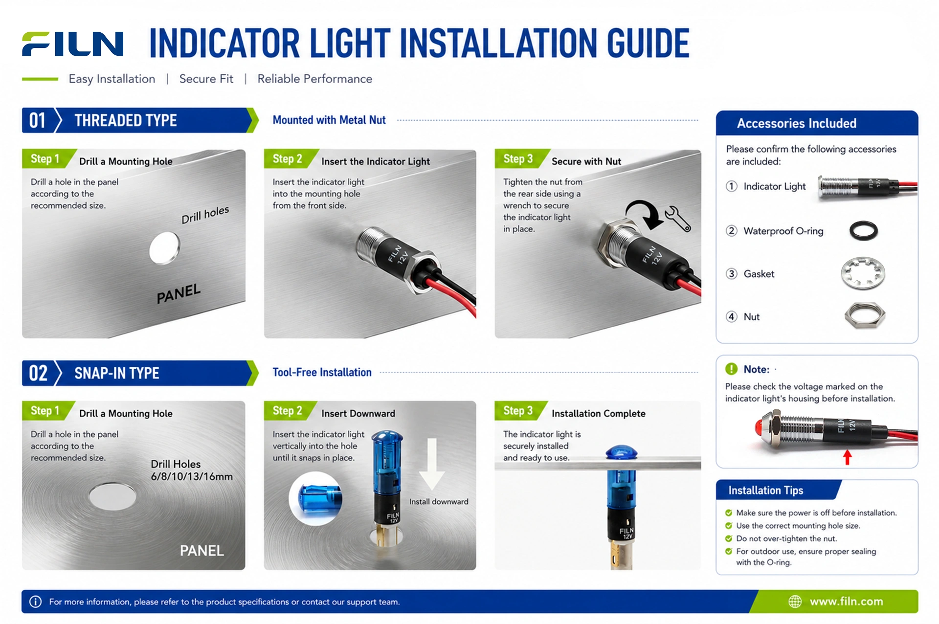
Follow this manual to mount the 8mm threaded flush point indicator light into a control panel assembly, ensuring a clean fit and reliable IP65 waterproof sealing:
- Isolate Main Power: Disconnect all primary power supplies and verify the work area is de-energized before starting the installation.
- Drill the Panel Cutout: Create a precise 8mm circular hole in the instrument panel using a step drill bit, then deburr the hole edges to remove sharp metal burrs.
- Fit the Sealing Washer: Slide the included silicone rubber O-ring onto the threaded metal indicator housing, seating it flat against the underside of the flush head.
- Insert the Unit: Pass the dual 20cm wire leads and the threaded barrel through the front of the 8mm panel cutout until the front seal rests flush against the panel surface.
- Install Backside Hardware: From behind the panel, slide the flat compression gasket over the wire leads and onto the threaded housing.
- Secure and Tighten: Thread the M6 metal hex nut onto the barrel and tighten it firmly with a wrench to compress the front silicone ring, establishing an IP65 moisture barrier.
- Connect Wire Leads: Splice the pre-wired 20cm pigtail leads directly into your control circuit using terminal blocks or insulated inline splices.
Electrical Termination & Terminal Comparison Matrix
Secure electrical connections are essential for preventing resistance variations or accidental circuit disconnects caused by structural vibrations. The table below compares the functional advantages of pin terminals, tab terminals, and integrated wire lead configurations:
| Connection Interface Style |
Primary Operational Advantages |
Potential Drawbacks / Constraints |
| Integrated Wire Leads (Pre-Wired 2PIN) |
Completely eliminates on-site soldering; allows direct connection to distant terminal tracks; highly resistant to pullout. |
Wire length is fixed at the factory (e.g. 20cm dual runs), requiring extensions if runs exceed the pre-wired limits. |
| Rigid Pin Terminals (Solder Pins) |
Provides a compact, lightweight footprint ideal for direct PCB soldering or targeted quick-mating multi-plugs. |
Requires manual hand soldering or specialized matching plug components during final enclosure wiring. |
| Spade / Tab Quick Connectors |
Enables fast field maintenance using standard female crimp sliders without requiring hot iron tools. |
Requires more depth behind the control panel face to clear the protruding tab connectors safely. |
When wiring pre-wired pigtail models, ensure reliable electrical contact by joining wires using spring-loaded lever blocks, standard crimp sleeves, or soldered inline splices wrapped with heavy-duty heat-shrink tubing. Always verify that all upstream power is fully disconnected before handling exposed conductors to prevent electrical shock or damage to the internal LED chip.
Industrial Signaling Knowledge Base
Understanding basic electrical engineering principles helps prevent common integration errors and extends the service life of panel components.
Mitigating Residual Voltage & Ghost Illumination
A common issue in complex automation panels is “ghost illumination,” where an LED indicator glows faintly even when its control circuit is turned off. This occurs because highly sensitive solid-state LED dies can be energized by small leakage currents, electromagnetic coupling from parallel AC wiring runs, or residual PLC leakage. To prevent ghost illumination, engineers can integrate a parallel bleeder resistor or a bypass zener diode circuit, which diverts low-level leakage currents away from the LED chip.
Enclosure Integrity & Chemical Resistance Standards
Selecting an indicator requires matching its ingress protection rating with the operating environment. Standard IP65 housings protect against light dust and low-pressure water sprays, making them suitable for typical indoor control setups. For harsher environments, such as food processing lines or chemical plants that undergo high-pressure washdowns, true IP67 or IP69K rated metal components are necessary to prevent moisture from passing the front panel seal and causing internal short circuits.
Procurement Decision Guide & Sourcing Insights
B2B procurement teams should evaluate the following technical parameters when selecting a status indicator to ensure long-term performance and system compatibility:
- Voltage Compatibility: Ensure the target electrical system voltage matches the internal resistor configuration (supporting 3V to 220V inputs) to maintain proper brightness and prevent overcurrent damage.
- Panel Clearance and Depth: Factor in the 40cm cumulative wire loop tail when mapping out internal conduit and cable tray paths behind the mounting surface.
- Regulatory Certifications: Confirm the indicator carries valid international credentials like CE, VDE, RoHS, ISO9001, and CCC to streamline system exporting and final equipment testing.
- Housing Material Durability: Choose ruggedized plated alloys or stainless steels over standard nylon or plastics for harsh, high-impact industrial settings.
Why B2B Engineers Specify FILN Components
FILN operates as a direct manufacturer, eliminating middleman markups to provide competitive volume pricing, custom electrical tailoring, and fast production lead times. With no strict Minimum Order Quantity (MOQ) limits, we help engineering teams smoothly scale from initial prototyping up to full mass production.
Founded in 2006, Yueqing Yulin Electronic Co., Ltd. (operating under the global brand name FILN) is based in Wenzhou, Zhejiang. Over the past two decades, we have grown into a specialized manufacturer integrating R&D, advanced production, and direct international sales across more than 100 countries. Operating a modern 10,000 m² facility with over 20 advanced production lines and an independent testing lab, our production processes follow the ISO9001 quality management system to ensure consistent component reliability.
Our certified product portfolio (UL, CE, RoHS, REACH, TUV, CB) is widely used in commercial food equipment, energy storage arrays, EV charging infrastructure, automotive sub-assemblies, marine panels, and security grids. Our engineering team provides direct support for custom designs, allowing buyers to quickly modify wire lengths, voltage configurations, or shell finishes.
Frequently Asked Questions
Q1: How do you prevent phantom illumination (faint glowing) in an equipment panel indicator?
A1: Phantom illumination is typically caused by induction from parallel AC power lines or minimal PLC leakage. This can be resolved by connecting an external parallel bleeder resistor across the pigtails, which bleeds off residual voltage below the LED’s turn-on threshold.
Q2: Can this IP65 equipment panel indicator withstand caustic chemical washdowns?
A2: Yes. The robust plated alloy casing combined with an integrated silicone ring seal is designed to handle common industrial sanitizers and spray washes without corroding or losing seal integrity.
Q3: What is the exact panel cutout dimension required for the FL1M-08FW-5 lamp?
A3: The unit requires a standard 8mm (0.315 inch) circular cutout. We recommend deburring the hole edges after drilling to ensure a clean, flush fit for the waterproof sealing ring.
Q4: Does the factory support custom operating voltages for this wire lead light?
A4: Yes. Our manufacturing facility can configure the internal resistor network to support any operating voltage ranging from 3V up to 220V AC or DC, matching your system requirements.
Q5: What are the insulation specifications for the pre-wired wire leads?
A5: Each indicator features dual 20cm pre-wired copper conductor wires insulated with industrial-grade PVC, providing high flexibility and excellent dielectric protection inside dense wiring trunks.
Q6: Why should I choose metal status indicators instead of traditional plastic models?
A6: Metal bodies provide high physical hardness, resist crack propagation under stress, and handle high temperatures without deforming, ensuring long-term durability in industrial environments.
Q7: What parts are included with a standard indicator light purchase?
A7: Each unit is supplied as a complete kit containing 1x metal indicator light body, 1x silicone waterproof ring, 1x flat compression washer, and 1x matching M6 locking hex nut.
Q8: Do these status indicator lights carry international compliance certifications?
A8: Yes, our entire production line is fully certified under CE, VDE, RoHS, ISO9001, and CCC standards, making them suitable for global market integration.
Q9: What is the estimated operational lifespan of the integrated point LED?
A9: The high-efficiency solid-state LED chip is designed to maintain consistent brightness for 50,000 to 100,000 hours of continuous service, minimizing ongoing maintenance overhead.
Q10: What head profiles are available for tailored panel designs?
A10: We manufacture flat heads, elevated convex heads, and recessed concave heads, allowing you to choose the right mechanical look and viewing angle for your specific panels.
Q11: Are there strict Minimum Order Quantity limits on custom corporate orders?
A11: No. FILN operates on a zero-MOQ policy, helping engineering teams source small batches for prototype evaluation before moving to volume purchasing.
Q12: How does the point-lit lens design improve control panel readouts?
A12: The distinct center point light gives a sharp, high-contrast visual signal, making it easier for operators to identify specific alerts on crowded instrument boards.
Q13: Which casing alloy is recommended for high-salinity marine environments?
A13: For applications exposed to coastal marine air or salt spray, we recommend specifying our stainless steel or chrome-plated copper housings for optimal corrosion defense.
Q14: What colors are available for the semiconductor LED cores?
A14: We provide five standard colors: Red (R), Green (G), Yellow (Y), Blue (B), and White (W) to align with global safety and operational guidelines.
Q15: What is the maximum safe working temperature range for these components?
A15: The indicators are rated to run reliably in environmental temperatures ranging from a low of -40°C up to a maximum upper ceiling of +80°C.
Q16: How much power does the FL1M-08FW-5 light draw under continuous operation?
A16: The module runs efficiently with a low operating current of 20mA or less, consuming only about 0.2 Watts of power per unit.
Q17: Can these components be used in low-voltage DC automation systems?
A17: Yes. While this version is optimized for tailored voltages, our factory can configure the internal resistor network to support low-voltage AC/DC lines down to 3V.
Q18: What polymer material is selected for the internal base component?
A18: We use high-purity Polyamide 66 (PA66 Nylon), which provides excellent mechanical insulation and high resistance to thermal deformation under continuous electrical loads.
Q19: How does the mounting assembly prevent the indicator from loosening over time?
A19: Each kit includes a stainless steel plum blossom lock washer that grips the rear panel face, preventing the indicator barrel from spinning or loosening under high mechanical vibration.
Q20: Where can I look at the broader range of ultra-compact 6mm metal indicator options?
A20: You can view our full range of compact panel indicators by visiting our dedicated catalog page at 6mm Metal Indicator Light Line Catalog Selection.