KEY TAKEAWAYS FOR ELECTRICAL ENGINEERS & BUYERS
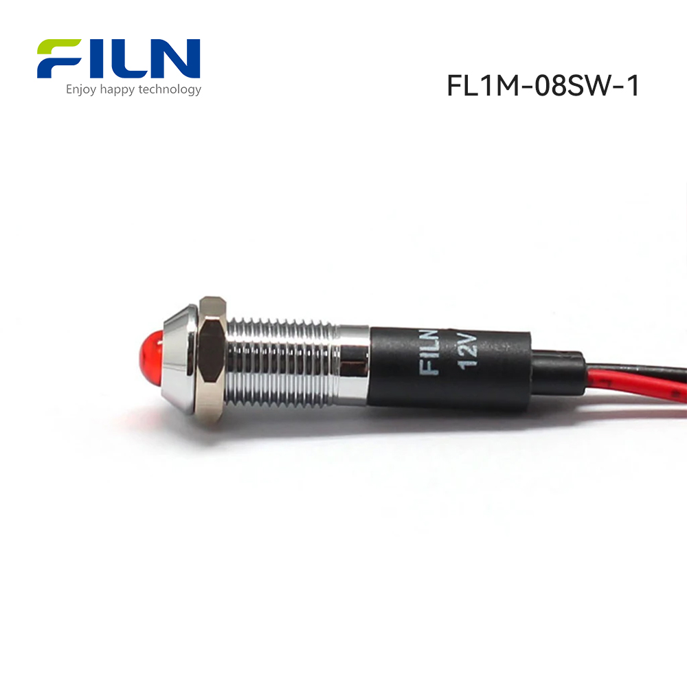
- Industrial Focus Model: Specifically engineered model FL1M-8SW-1 optimized for direct factory B2B procurement pipelines.
- Standardized Mounting: Exact 8mm (0.31 inch) panel cutout dimension ensures drop-in compatibility with legacy industrial layouts.
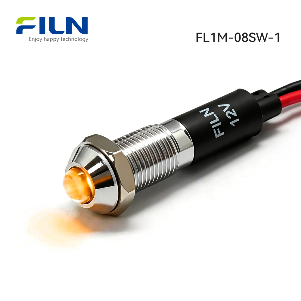
- Convex Visibility Advantage: Raised head projection ensures enhanced multi-angle luminosity across expansive automated assembly floors.
- Flexible Input Voltages: Complete engineering support for custom inputs stretching across the 3V to 250V AC/DC operational spectrum.
- Pre-Wired Layout: Equipped with dual 20cm PVC wire leads (40cm aggregate) to accelerate control panel build cycles.
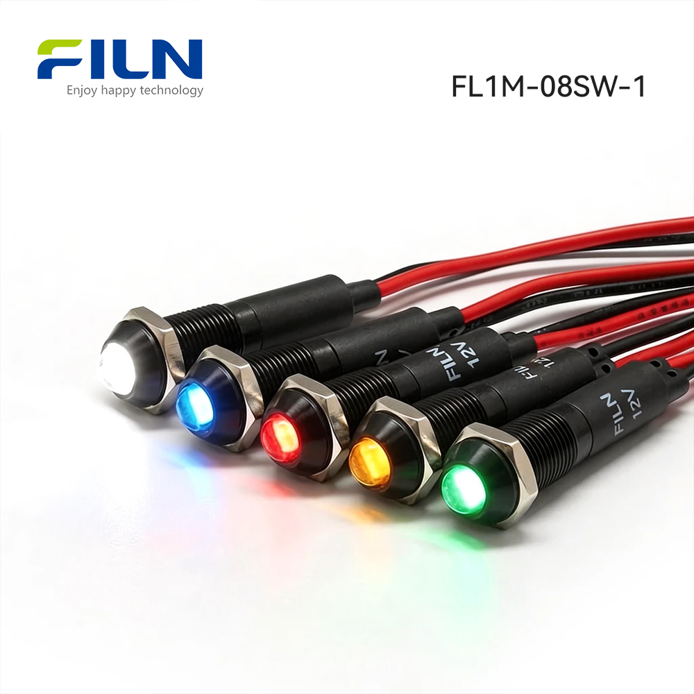
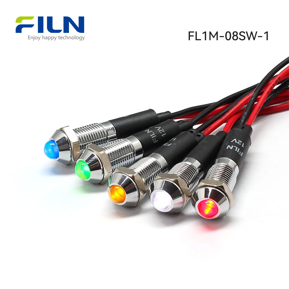
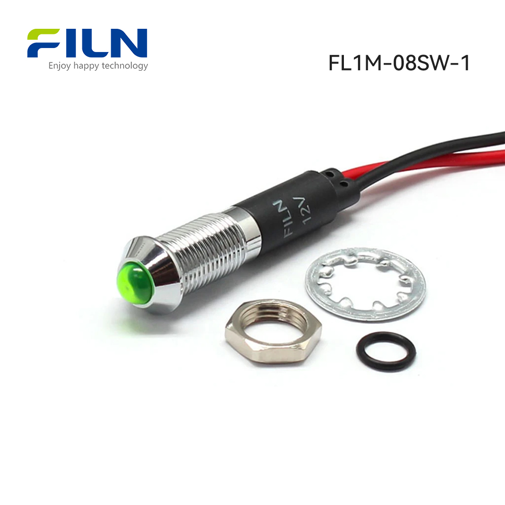
- Premium Housing Profiles: Choice of traditional silver-plated brass alloy or ultra-durable black-anodized zinc-aluminum structures.
- Complete Ingress Shielding: Achieves documented IP65/IP67 ratings to successfully reject environmental moisture, oil, and dust particles.
- Global Certification Portfolio: Fully backed by validated UL, CE, VDE, RoHS, and ISO9001 compliance standards for export assurance.
- Zero Procurement Boundaries: Flexible manufacturing layout featuring no minimum order quantity constraints for custom specifications.
- Direct Factory Support: Managed directly from our ISO9001 manufacturing center with full access to secondary CAD data and testing records.
WHAT IS A YELLOW INDICATOR LIGHT?
A yellow indicator light is a specialized industrial optoelectronic signaling device designed to provide real-time status feedback, warning telemetry, or process anomalies within an electrical circuit topology. Functioning as a critical interface on control system interfaces, its structural architecture comprises a high-intensity semiconductor LED chip, an internal current-limiting voltage resistor network, and a rugged mechanical body structure tailored for panel mounting. By emitting a distinct wavelength within the 585-595nm visual range, it fulfills the necessary alert criteria required by modern industrial automation safety regulations.
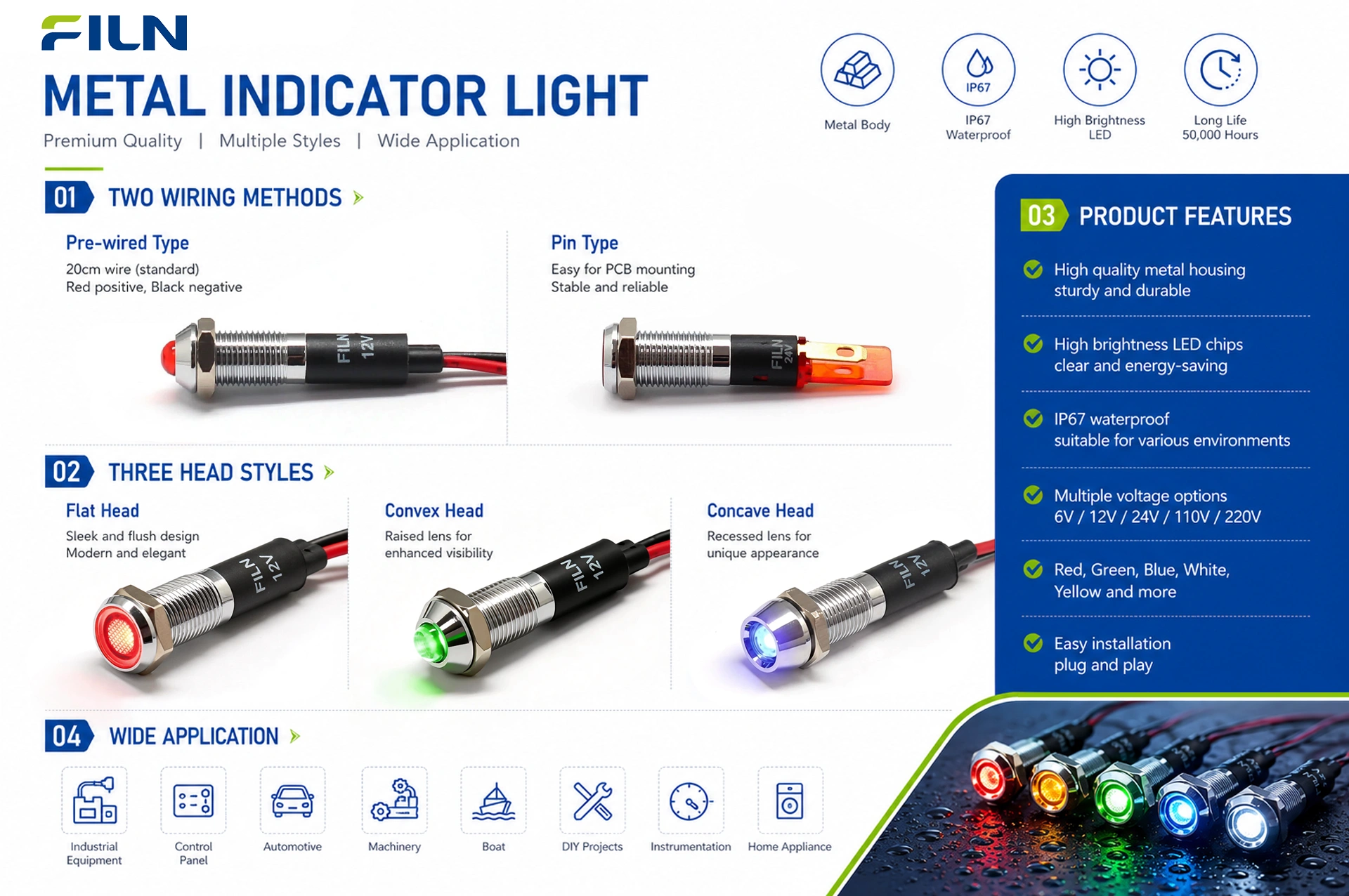
FILN provides an extensive array of panel signaling variations, maintaining fully diversified production lines for both high-end metal indicator lights and cost-effective structural plastic configurations. Mounting diameters span standard sizing boundaries from micro 6mm cutouts up to large-scale 30mm control console apertures. Wiring formats are split between traditional dual-pin solder terminals and fully insulated direct wire lead assemblies. For specialized mechanical designs, our metal housing architectures are produced in three distinct optical profiles: low-profile flat head, maximum-visibility convex raised head, and recessed concave head configurations, allowing mechanical layout engineers to precisely match panel structural clearance and sightline requirements.
PRODUCT OVERVIEW & TECHNICAL PRINCIPLES
The FILN FL1M-8SW-1 functions as a heavy-duty, panel-mounted optoelectronic node designed to convert raw secondary electrical signals into a definitive, color-coded visual reference point. Utilizing an advanced solid-state LED semiconductor, the component routes incoming line currents through an integrated carbon-film resistance matrix that successfully absorbs transient surges while preventing terminal degradation. Its underlying mechanical design integrates a micro-threaded barrel arrangement secured via an included heavy-torque hexagonal locking nut, completing a reliable structural mount that fully isolates internal electronics from panel-induced sheer stressors.
Electrically, the unit contains a highly efficient, single-diode light matrix that delivers a balanced luminous flux while drawing negligible power, averaging approximately 0.2W at standard nominal ratings. The primary applications for this specific 8mm convex layout include hazardous area alert nodes, high-vibration power distribution racks, remote telemetry tracking panels, and commercial food-processing enclosures. By wrapping this circuit within an alloy shell coupled with high-temperature PA66 nylon base matrices and a clear polycarbonate diffuser lens, the unit reliably achieves broad compliance across UL, CE, and VDE test structures, ensuring stable field operation within extreme manufacturing sectors.
QUICK SPECIFICATIONS MATRIX
| Parameter Profile |
Technical Specification Data |
| Product Description |
Metal indicator light with wire leads |
| Model Designation |
FL1M-8SW-1 |
| Mounting Hole Diameter |
8mm / 0.315 Inches |
| Operational Voltages |
3V to 250V AC/DC (Custom Engineering Adaptation Matrix) |
| LED Illumination Colors |
Yellow (Primary), Red, Green, Blue, White, Bi-Color, Tri-Color Options |
| Waterproof Ingress Protection |
IP65 / IP67 Sealed Specification Barrier |
| Wiring Termination Type |
2-PIN Direct Integrated Wire Lead Layout (Dual 20cm Leads, 40cm Total) |
| Optical Head Configuration |
Convex Head / Raised Profile Lamp Dome |
| Surface Finishing Quality |
Smooth, uniform surface completely free of burrs, oxidation defects, or structural fractures. |
| Mechanical Assembly Integrity |
The lens assembly and internal base elements are precisely swaged; no relative axial rotation, mechanical displacement, or structural distortion is present. |
COMPONENT MATERIALS METALLURGY
| Accessory Part Name |
Material Composition |
Engineering Purpose & Justification |
| Outer Shield Barrel (Shell) |
Nickel-Plated Copper Alloy / Black-Anodized Zinc-Aluminum Alloy |
Provides premium impact shielding, total resistance to surface oxidation, and optimal grounding. |
| Internal Lamp Holder Base |
Polyamide 66 (PA66 Nylon Matrix) |
Ensures high thermal resistance, outstanding physical rigidity, and complete dielectric isolation. |
| Optical Lens Cover (Lampshade) |
High-Grade Polycarbonate (PC) |
Delivers elite light transmission, total UV stabilization, and high anti-shatter characteristics. |
| Primary Luminescent Source |
High-Brightness Solid-State LED Chip |
Generates localized chromatic purity, low operating heat dissipation, and extensive operational lifespans. |
| Internal Ballast Element |
High-Stability Carbon Film Resistor |
Regulates current delivery safely to secure steady brightness margins during line fluctuation. |
| Conductor Lines (Wireway) |
Polyvinyl Chloride (PVC Insulated Cooper Core) |
Provides excellent conductor flexibility, easy routing, and rapid splicing access. |
| Locking Fastener (Nut) |
Machined Brass/Copper Alloy |
Prevents thread stripping when exposed to high-torque mechanical pneumatic installation drivers. |
| Compression Washer (O-ring) |
Premium Industrial-Grade Silica Gel |
Maintains elastomeric seal integrity across extended temperature boundaries to block fluid ingress. |
| Lock Washer |
Plum Blossom Stainless Steel Gasket |
Bites into back panel sub-strata to defeat rotational loosening from constant machine vibration. |
CHIP LEVEL LED SPECIFICATIONS
1. Absolute Maximum Ratings
| Critical Diode Operating Boundaries |
Maximum Safety Limit Target |
| Maximum Forward Current (IFP) |
20 mA |
| Allowable Reverse Breakdown Voltage (VR) |
5 V |
| Maximum Absolute Power Dissipation (PD) |
60 mW |
| Operating Temperature Limitation Window (TOPR) |
-40°C to +80°C |
| Storage Temperature Matrix Boundary (TSTG) |
-40°C to +100°C |
| Lead-Free Solder Thermal Limit (TSOL) |
Maximum 260°C maintained for no more than 3 consecutive seconds |
2. Electro-Optical Performance Characteristics
| Electro-Optical Test Metric |
Assigned Measurement Conditions |
Documented Parameter Limits (Ta=25°C) |
| Forward Operating Voltage (VF) |
IF = 20 mA Drive Circuit |
Minimum: 2.8 V | Maximum: 3.2 V |
| Leakage Reverse Current (IR) |
VR = 5 V Reverse Baseline |
Maximum Ceiling Threshold: 5 μA |
| Viewing Angular Divergence (2θ1/2) |
IF = 20 mA Drive Circuit |
Typical Value Metric: 60° |
| Luminous Output Intensity |
IF = 20 mA Drive Circuit |
Minimum: 500 mcd | Maximum: 800 mcd |
| Recommended Working Drive (IF) |
Continuous Direct Steady-State Run |
Nominal Target: 20 mA |
| Dominant Chromatic Wavelength |
IF = 20 mA Drive Circuit |
Yellow Peak Spectrum Window: 520 nm to 525 nm |
| Maximum Junction Temperature (Tj) |
IF = 20 mA Continuous Run |
Maximum Internal Ceiling: 125°C |
| Structural Thermal Resistance (RJP) |
IF = 20 mA Node Condition |
Typical Junction to Pin Rating: 8°C/W |
STANDARD ATMOSPHERIC DATA CALIBRATION BASELINE
Unless specifically detailed in supplementary validation documents, all electrical, physical housing, and secondary optical performance metrics are gathered under the following uniform laboratory atmospheric criteria:
| Atmospheric Parameter Node |
Calibrated Base Environment Target |
| Ambient Room Temperature |
5°C to 35°C Operational Verification Window |
| Relative Air Humidity Profile |
45% to 85% Absolute Structural Limits |
| Ambient Barometric Pressure |
86 kPa to 106 kPa (Equivalent to 860 mbar to 1060 mbar) |
Technical Laboratory Notes: Luminous intensity outputs and dominant wavelength tracking bands are calibrated in absolute compliance with standard CIE international optical eye response criteria. Allowable measurement instrument tolerances are explicitly set to ±15% for absolute luminous intensity and ±0.1V for all baseline forward voltage tracking structures.
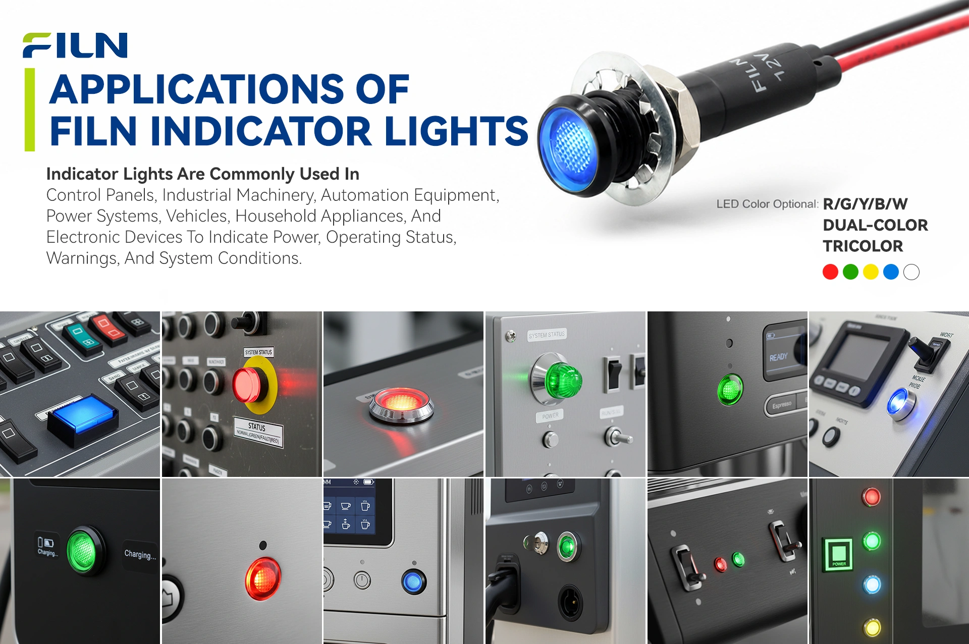
INDUSTRIAL APPLICATIONS BY SECTOR
Constructed around a high-tensile copper alloy or a specialized stainless-steel shell structure, the FILN metal pilot light assembly delivers extreme physical protection coupled with a fully verified IP67 ingress protection rating. Unlike standard plastic alternative lights that suffer from premature cracking, solar discoloration, and heat distortion under load, these robust metal indicators offer reliable, multi-year performance across heavy manufacturing platforms.
1. Industrial Automation & Heavy Machining Operations
This sector represents the highest deployment baseline for heavy-duty metal pilot lights due to the continuous presence of structural vibrations, cutting oils, and mechanical impacts. On CNC mills, automated routing units, and complex PLC electrical chassis, our 8mm convex indicator displays critical caution telemetry. The integrated wire lead system bypasses legacy pin-soldering weak points, preventing conductor shearing under constant machine resonance.
2. Outdoor Power Systems & EV Charging Infrastructures
Outdoor grid installations demand total UV stabilization and resistance to wide temperature shifts. In commercial EV fast-charging pillars and solar combiner enclosures, these lights communicate status codes (such as charging process cycles or ground fault warnings) across a verified -40°C to +80°C climate window, ignoring heavy rain, snow, and urban pollution.
3. Transit Systems, Engineering Vehicles, & Marine Consoles
Heavy earthmoving vehicles, railway cabs, and maritime instrumentation decks subject components to severe shock and aggressive salt-spray corrosion. FILN metal configurations utilize specialized marine-grade plating and integrated rear potting to block water ingress, keeping critical diagnostics—such as fluid pressure warning metrics—fully functional in harsh offshore operations.
4. Public Vending Enclosures & Safe-Area Dispensing Terminals
Publicly accessible hardware requires components with high impact resistance to prevent deliberate vandalism and rough handling. When mounted to automatic ticketing systems, fuel-dispensing terminals, or outdoor access control panels, the robust metal casing provides excellent impact isolation, protecting internal circuitry and ensuring long-term operational uptime.
5. Clinical Apparatus & Food Processing Equipment
Sterile processing and food preparation facilities rely on high-pressure hot water washes and chemical sanitizers. The IP67-rated silicone seal arrangement on these indicator lights protects internal components against water jets, while the smooth metallic body avoids trapping biological contaminants, making it an excellent fit for medical sterilization systems and packaging lines.
CHROMATIC SIGNALING STANDARDS
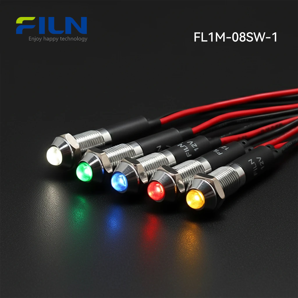
Industrial control environments rely on clear, standardized color coding to prevent operator error and speed up diagnostic response times. FILN produces five primary single-chroma light outputs (Red, Green, Yellow, Blue, White) along with advanced multi-color configurations to serve complex automated systems.
Yellow Illumination (Warning/Anomaly State): This color denotes a critical transitional phase, non-standard operating parameter, or an impending safety threshold crossing. It indicates that the machinery is operating outside its ideal performance zone (e.g., thermal overload warning or fluid bypass activation) without immediately halting the system, prompting operators to intervene before an emergency shutdown occurs.
Red Illumination (Danger/Emergency Failure): Identifies a total system fault, emergency trip activation, or immediate safety hazard. It demands instant operator response to protect personnel and prevent mechanical damage.
Green Illumination (Normal Safe Runtime): Confirms that the monitored system is operating within safe, standard parameters. It indicates a ready state or optimal closed-loop operation.
Blue Illumination (Mandatory Operator Action Required): Signals that a specific manual procedure must be completed, such as resetting a sequence timer, loading material inputs, or executing a calibration step.
White Illumination (System Voltage Telemetry): Serves as a general status indicator confirming line voltage availability or tracking active system distribution nodes without implying a change in process state.
For space-constrained control consoles that require complex status tracking, FILN designs integrated bi-color and tri-color LED structures within a single 8mm housing, enabling multiple distinct color alerts from one mounting point.
CHASSIS MECHANICAL INSTALLATION WORKFLOW
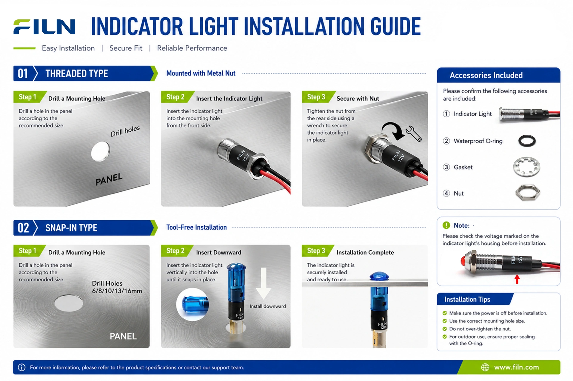
Follow this step-by-step procedure to properly mount the FL1M-8SW-1 convex indicator light into an industrial control panel, ensuring a secure fit and reliable ingress sealing.
- Execute Panel Cutout: Drill a precise 8mm (0.315 inch) circular mounting hole into the control panel surface using a calibrated step bit or punch tool. Ensure the hole edges are thoroughly deburred to prevent damage to the sealing gasket.
- Position Ingress Gasket: Slide the provided silicone waterproof O-ring over the rear wire leads and position it flush against the underside of the convex metal head assembly.
- Insert Component Base: Route the 2-pin wire leads down through the prepared panel cutout from the front side, sliding the threaded metal barrel into place until the silicone gasket seats flat against the faceplate.
- Install Mechanical Lock Washers: From behind the panel, slide the star/plum-blossom lock washer over the wire harness and onto the threaded barrel to provide vibration resistance.
- Tighten Securing Hex Nut: Thread the brass backing nut onto the barrel by hand, then torque it securely using a deep-well socket wrench to compress the front silicone seal and complete the IP67 ingress protection assembly.
- Perform Termination Connection: Strip the lead ends to prepare them for integration into the control circuit via terminal blocks, inline splices, or direct soldering.
ELECTRICAL COUPLING & TERMINATION CRITERIA
Industrial indicator lights are typically wired using either rigid male spade solder lugs or direct, integrated flexible wire harnesses. Wire lead models like the FL1M-8SW-1 simplify panel assembly by providing pre-installed conductor leads that eliminate the need for manual terminal soldering, which can become brittle and fail in high-vibration environments.
To connect pre-wired units, strip the outer insulation jacket from the 20cm dual-line leads to expose the copper core. Secure the wire ends to the system circuit using industrial push-in terminal blocks, crimped inline butt splices, or a soldered joint wrapped in dual-wall polyolefin heat-shrink tubing. This ensures stable current flow and protects the connection from oxidation and mechanical strain.
⚠️ CRITICAL SAFETY DIRECTIVE: Always isolate and lock out the main power distribution circuit before servicing or making wiring connections to an electrical panel. Verify that the system is de-energized with a calibrated voltmeter to ensure compliance with plant safety regulations.
INDUSTRIAL SIGNALING KNOWLEDGE CENTER
Understanding Phantom Illumination: High-density control panels can experience a phenomenon known as “phantom illumination” or faint glowing, where an LED indicator remains partially lit even when the control switch is open. This is typically caused by induced stray voltages or leakage currents traveling through long, parallel wire runs next to active AC power lines. FILN resolves this issue by tuning the internal carbon-film resistor matrix to bleed off low-level induced currents, ensuring the LED only illuminates when receiving full nominal control voltage.
Combating Ingress Failure Modes: Washdown environments can drive water past weak seals via thermal capillary action. When an indicator light heats up during operation and then rapidly cools down from a cold water spray, an internal vacuum can form that draws in moisture. FILN mitigates this risk by utilizing high-durometer silicone O-rings and gas-tight rear potting compound, maintaining a reliable seal under severe thermal shock conditions.
Routine Preventive Maintenance: While solid-state LEDs do not suffer from sudden filament burnouts like old incandescent bulbs, they can experience gradual lumen depreciation over time. Maintenance schedules should include regular visual checks to confirm adequate contrast brightness, along with torque inspections of the rear securing nut to ensure structural grounding remains solid against panel vibration.
SPECIFICATION & B2B PROCUREMENT GUIDE
When procuring status indicators for large-scale equipment manufacturing, engineering teams should evaluate several critical design parameters to ensure long-term field reliability:
- Voltage Matching: Verify nominal system voltage (e.g., 12VDC, 24VDC, 110VAC, or 220VAC) to specify the correct internal resistor matrix.
- Optical Sightlines: Choose a raised convex head profile for wide, multi-angle visibility, or a flat head design for flush, low-profile panels.
- Housing Material: Select nickel-plated brass for general corrosion protection, or black-anodized zinc-aluminum alloy to reduce reflections on dark control surfaces.
- Conductor Specification: Confirm required wire lead lengths (standard 20cm or custom lengths) to allow direct routing without mid-run splicing.
FILN streamlines B2B procurement pipelines by offering full component customization, rapid prototyping, and comprehensive safety certifications (UL, CE, VDE), helping engineering teams maintain compliance and meet tight project deadlines.
WHY INDUSTRIAL SPECIFIERS TRUST THE FILN FACTORY DIRECT ECOSYSTEM
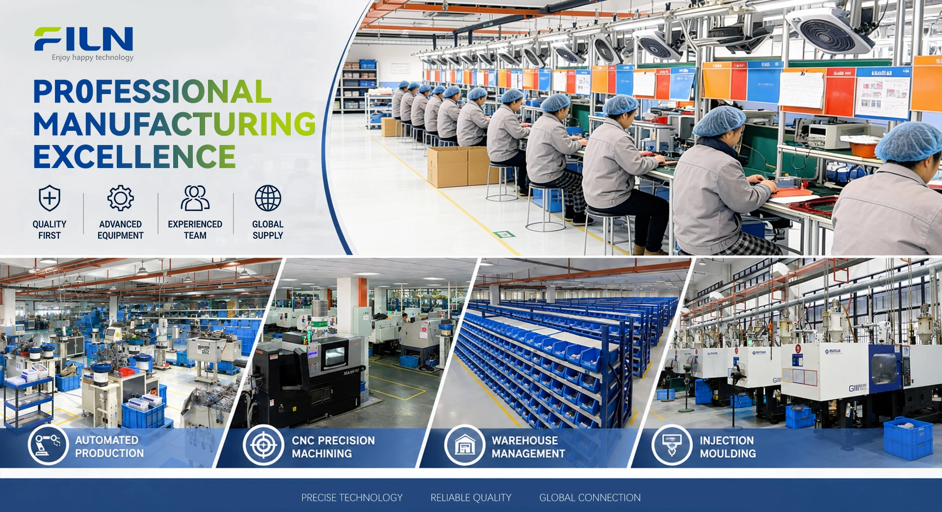
Yueqing Yulin Electronic Co., Ltd. (operating globally under the premium FILN brand name) was established in 2006 in Wenzhou, Zhejiang, evolving into a world-class manufacturing enterprise specializing in high-performance electromechanical switches and panel signal indicators. Spanning a modern 10,000 square meter production facility, FILN manages more than 20 advanced, automated production lines alongside an independent, certified testing laboratory. Our manufacturing workflows are structured in strict compliance with the ISO9001 Quality Management System, enabling us to export reliable, high-performing components to industrial clients across more than 100 countries.
Our diversified production lines manufacture an extensive range of compact electrical components, including metal indicator lights, push-button switches, rocker switches, and toggle switches, alongside fully integrated custom wire harness assemblies. Backed by key international safety certifications including UL, CE, VDE, RoHS, SGS, and TUV, FILN components are widely specified across demanding industries such as heavy commercial kitchen appliances, green energy storage installations, EV charging infrastructure, automotive sub-systems, marine control panels, and critical security systems. By maintaining a zero-MOQ policy, providing rapid engineering support, and offering direct factory-to-business shipping, FILN helps global OEMs and system integrators optimize their procurement and reduce assembly lead times.
Direct Communication Channels:
FREQUENTLY ASKED QUESTIONS
Q1: How do you prevent phantom illumination (faint glowing) in 12v LED indicators?
A: Phantom illumination is caused by induced voltage leakage from parallel AC lines or high-density wire tracks. FILN engineers mitigate this issue by integrating a precisely tuned carbon-film resistor within the indicator body, which bleeds off residual leakage currents and ensures the LED only lights up when receiving its nominal control signal.
Q2: Can this IP67 indicator light be washed down with caustic chemicals?
A: Yes. The FL1M-8SW-1 features a nickel-plated brass or black-anodized zinc-aluminum alloy shell combined with a high-durometer silicone sealing gasket. This combination safely resists standard chemical washdowns and high-pressure sprays common in food processing and laboratory environments.
Q3: What is the exact mounting hole size for the FL1M-8SW-1 yellow indicator light?
A: This model requires a precise 8mm circular panel cutout diameter, which is equivalent to approximately 0.315 inches.
Q4: Can the operational voltage be customized for non-standard power supplies?
A: Yes. As a direct factory manufacturer, FILN can engineer internal resistor configurations to match any operating voltage within a 3V to 250V AC/DC range based on your project requirements.
Q5: What standard wire length comes with this indicator light?
A: The standard configuration includes a 2-pin wire lead setup with dual 20cm lines (providing a 40cm aggregate wiring loop). Custom wire lengths can be specified for volume OEM orders.
Q6: What is the main visibility benefit of a convex head over a flat head design?
A: The raised convex lens extends past the panel surface, allowing the light to be seen from wider side angles and across large factory floors, whereas flat heads are designed for clean, low-profile visibility.
Q7: Does FILN enforce a minimum order quantity (MOQ) for custom voltages or wire modifications?
A: No. FILN operates with a flexible production layout that features no minimum order quantity boundaries, allowing procurement teams to easily source small test samples or execute large-volume production runs.
Q8: Which international safety and environmental certifications back this product?
A: The FL1M-8SW-1 indicator light is fully backed by validated UL, CE, VDE, RoHS, and ISO9001 compliance certifications.
Q9: Are the internal components well-protected against heavy machine vibration?
A: Yes. The combination of an integrated wire-lead termination system, a solid metal alloy body, and an internal PA66 nylon core protects internal components from failing under constant heavy mechanical vibration.
Q10: Is it possible to receive full 3D CAD files before placing a bulk procurement order?
A: Yes. Our engineering team can provide complete 3D CAD files, material data sheets, and official testing reports to assist with your panel layout design. Please contact us at inquiry@cnylin.com.cn.
Q11: What color choices does FILN offer for this metal pilot light series?
A: We offer five standard individual colors: Red, Green, Yellow, Blue, and White, along with advanced custom dual-color and tri-color configurations within a single housing.
Q12: What housing material finishes can be selected for this model?
A: Buyers can choose between a classic nickel-plated brass shell or a premium black-anodized zinc-aluminum alloy body finish.
Q13: How is the rear lock washer designed to prevent mechanical loosening?
A: Every light is supplied with a multi-point plum-blossom stainless steel lock washer that grips the back panel surface to resist loosening from machinery vibrations.
Q14: What is the expected operational running lifespan of the built-in LED chip?
A: The solid-state LED chip is rated for an operational lifespan of 50,000 to 100,000 hours of continuous runtime under normal conditions.
Q15: What average power draw can be expected during continuous system operation?
A: The energy-efficient internal circuit draws an average of just 0.2 Watts during standard operation at nominal current levels.
Q16: Can these indicator lights be deployed safely in extreme cold storage settings?
A: Yes. All FILN metal indicator models undergo thermal laboratory testing and are certified to operate reliably down to a minimum temperature threshold of -40°C.
Q17: What material is used for the optical light lens assembly?
A: The translucent lens dome is molded from high-impact polycarbonate (PC) plastic, providing excellent light transmission along with resistance to cracking and UV yellowing.
Q18: Where are these components engineered and manufactured?
A: All premium FILN products are engineered and produced directly at our 10,000 square meter, ISO9001-certified manufacturing plant located in Wenzhou, Zhejiang, China.
Q19: How are sample requests handled for evaluation during new project layout phases?
A: We provide free product samples to qualified engineering firms and OEM procurement buyers. You can request samples by emailing us directly at inquiry@cnylin.com.cn.