Key Engineering Takeaways
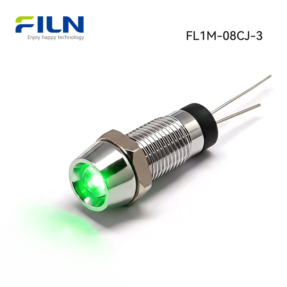
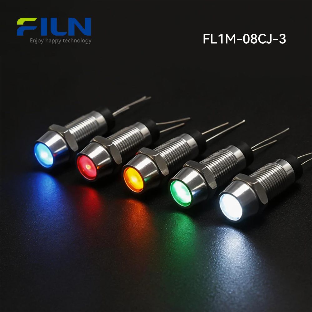
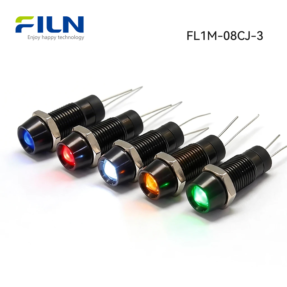
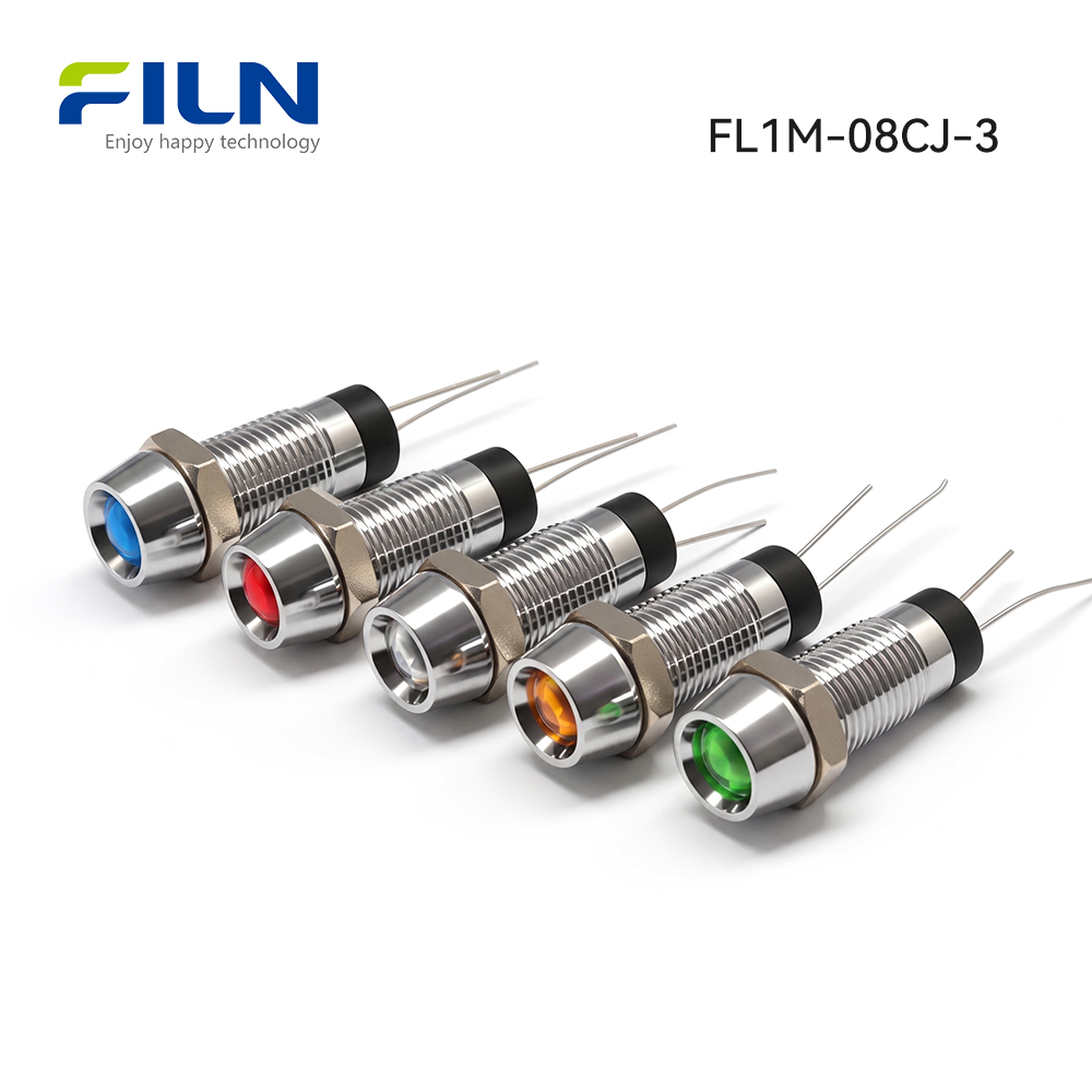
- Heavy-Duty Shell Construction: Available in high-strength silver-toned copper alloy or premium black-anodized zinc-aluminum alloy to resist extreme mechanical impact.
- Optimized Concave Optics: The 8mm concave head profile focuses the LED illumination directly outward, preventing lateral glare and ensuring clear visibility on dense control panels.
- Secure 2PIN Terminal Interface: Equipped with robust 2PIN solder/quick-connect pin terminals that prevent wire tension failure and optimize automated wiring assembly.
- Multi-Voltage Configuration: Optimized for standard 24V DC/AC operations with continuous support for custom wide-range voltages from 3V up to 220V based on specialized schematic designs.
- Comprehensive Environmental Defense: Features a high-integrity silicone O-ring and precise M6 threading to achieve an IP67 waterproof and dustproof sealing threshold.
- Extended Operating Lifespan: Integrated premium solid-state LED chips combined with carbon film resistors deliver a continuous operational lifespan of 50,000 to 100,000 hours.
- Global Compliance Profiles: Certified under CE, VDE, RoHS, CCC, and ISO9001 frameworks to comply with rigorous import and safety mandates across North America and Europe.
- Direct Industrial Sourcing: Manufactured and supplied directly from the FILN production facility with zero MOQ restrictions, ensuring lower overhead for prototype development and large OEM runs.
Understanding 24v LED Panel Indicator Lights
Industrial 24v led panel indicator lights are specialized optoelectronic signaling components designed to provide unmistakable real-time status feedback from within automated electrical circuits. Unlike basic commercial lamps, these heavy-duty pilot lights act as the primary visual interface between industrial machine logic and human operators. Their architectural framework consists of a solid metallic housing, an internal light-emitting diode (LED), an integrated current-limiting resistor, an impact-resistant lens, and electrical termination points. By converting electrical currents into highly visible, color-coded light signals, these panels communicate system readiness, processing states, active hazards, or complete operational failure across complex machinery setups.
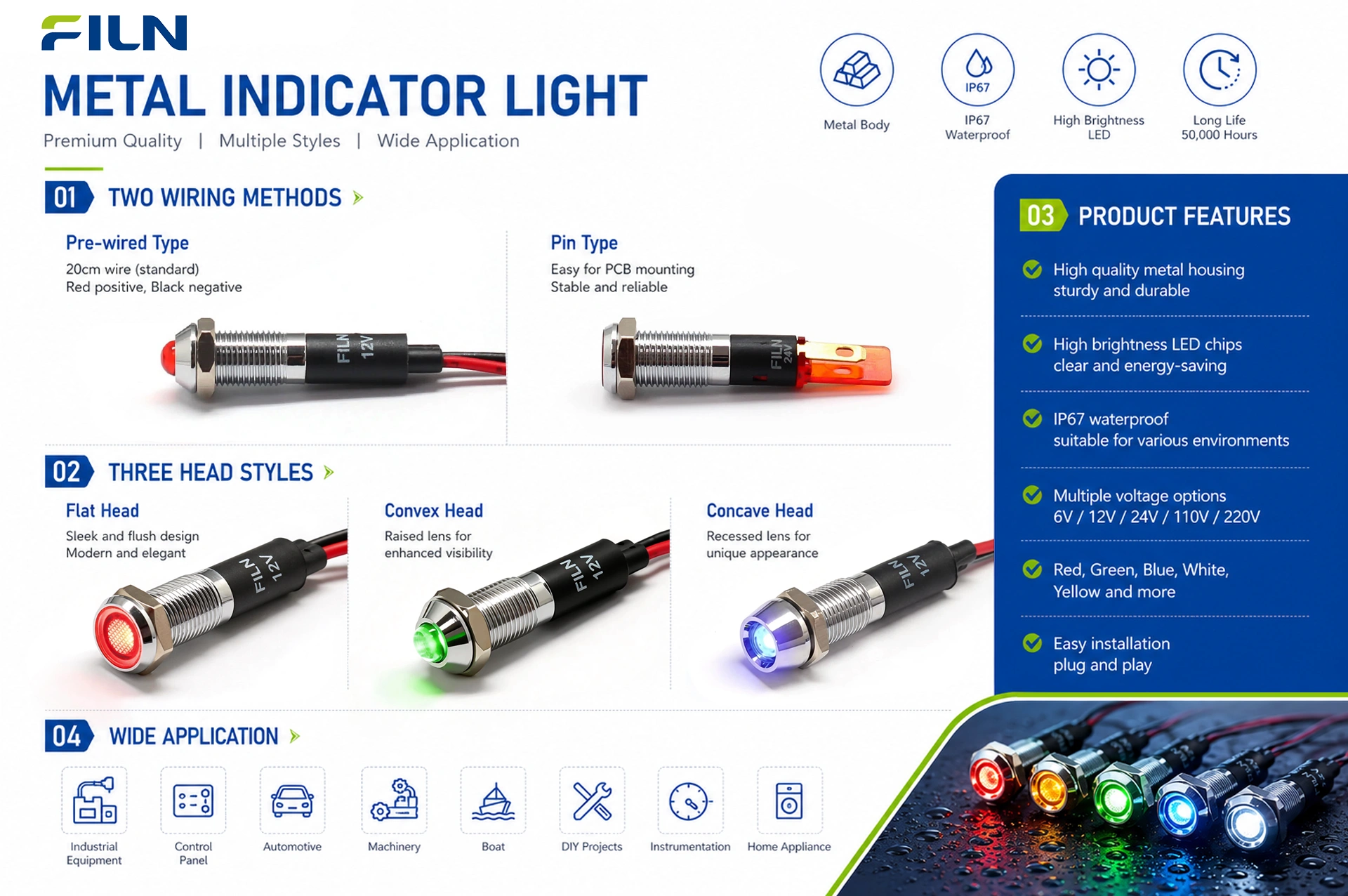
Engineers selecting industrial illumination solutions can choose between lightweight plastic indicator variants and high-durability metal indicators. FILN provides a versatile manufacturing spectrum featuring mounting hole diameters ranging from ultra-compact 6mm configurations up to heavy-duty 30mm designs. To support diverse electrical architecture and wiring protocols, these indicators are built with either direct wire leads or integrated 2PIN terminal pins. The metal indicator sub-category is further refined into flat-head, prominent round-head, and protective concave-head geometric styles, permitting mechanical designers to align their visual interfaces with exact physical layout requirements.
Industrial Product Overview
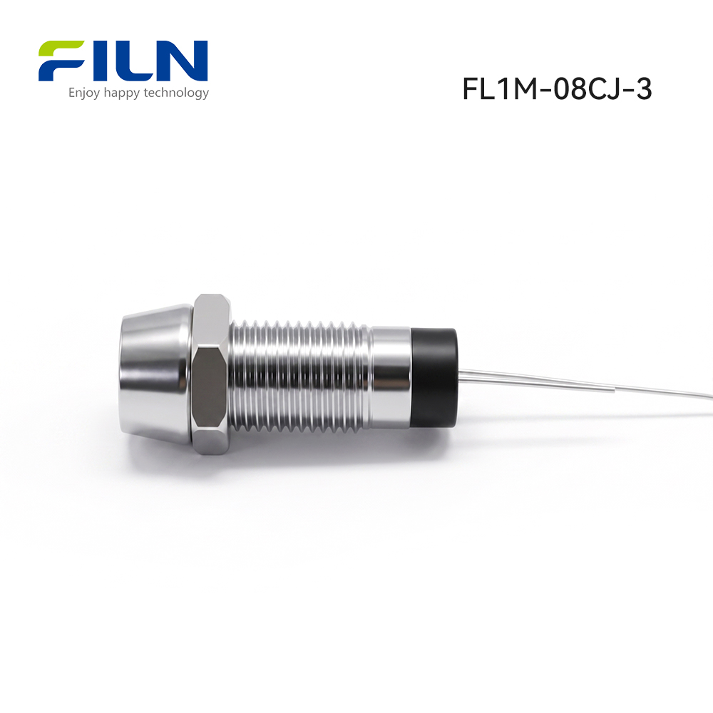
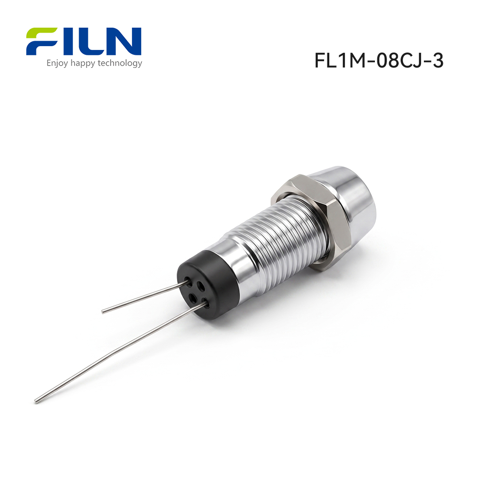
The FILN FL1M-08CJ-3 represents a premier iteration of 24v led panel indicator lights, specifically optimized for high-density panel arrays. Mechanically, the unit utilizes a single-nut thread-mounting mechanism that fits standard 8mm (0.31 inch) circular cutouts, compressing a high-elasticity silicone washer to eliminate path gaps for water ingress. Electrically, its 2PIN terminal layout facilitates instant integration into circuit schemes utilizing point-to-point soldering or quick-slide connector sleeves, eliminating the risk of internal circuit stress common with field wire management.
Constructed with a premium protective concave-head geometry, this metal indicator shields the optical lens from direct diagonal impact, making it ideal for low-clearance console configurations in processing facilities and laboratory environments. Certified under international standards such as CE, VDE, RoHS, and CCC, the indicator relies on solid-state LED dies that maintain constant luminosity even under mild input voltage fluctuations. This robust structural choice eliminates the thermal degradation and structural embrittlement that cause premature failure in legacy polycarbonate indicators when exposed to aggressive industrial washdowns.
Quick Specifications
| Specification Parameter |
Technical Data / Engineering Standard |
| Product Name (Description) |
Metal Pin Indicator Light |
| Model Designation |
FL1M-08CJ-3 |
| Mounting Hole Diameter |
8mm / 0.315 Inches |
| Operational Voltages |
Standard 24V (3V to 220V Customizable Range) |
| Available LED Colors |
Red (R) / Green (G) / Yellow (Y) / Blue (B) / White (W) |
| Waterproof Protection Rating |
IP65 / IP67 Enclosure Seal Compliance |
| Wiring and Termination Type |
2PIN Solder Lug / Pin Terminal Type |
| Head Profile Geometry |
Concave Head (Protective Inner Bezel) |
| Surface Quality Finishing |
Oxidation-free, micro-polished surface, devoid of fractures or metallic burrs |
| Assembly Integrity |
Interlocking head-to-base component anchoring; zero rotation or alignment skewing |
Performance Parameters
| Operational Parameter |
Target Threshold Values |
| Rated Working Voltage Range |
3V–240V DC / AC (Custom engineering supported) |
| Alternating Current Frequency Range |
50 Hz ~ 60 Hz Range |
| Rated Operational Current |
≤ 20 mA Max Current |
| Rated Electrical Power Dissipation |
Approximately 0.2 W |
| Insulation Resistance Bound |
≥ 100 MΩ (Verified at DC 500V between terminal pins and chassis outer shell) |
| Dielectric Strength Threshold |
1500V ~ 1800V AC; zero flashover phenomenon or insulation breakdown |
| Continuous Operating Lifespan |
50,000 Hours ~ 100,000 Hours solid-state life |
| Ingress Protection Level |
IP67 Water Immersion & Particle Proofing Rated |
Component Materials Breakdown
| Component Part Name |
Material Selection |
Engineering Justification |
| Chassis Outer Shell |
Copper Alloy (Chrome Plated) / Zinc-Aluminum Alloy (Anodized Black) |
Provides mechanical resistance to impacts and prevents atmospheric oxidation. |
| Internal Lamp Holder |
PA66 Polyamide Nylon Nylon |
Ensures superior dielectric insulation properties and thermal stability. |
| Optical Lampshade / Lens |
Polycarbonate (PC Polymer) |
Guarantees high optical transparency with UV-aging resistance and fracture toughness. |
| Luminescent Source |
High-Brightness Solid-State LED |
Offers efficient illumination output with minimal thermal generation. |
| Current Resistor Element |
Carbon Film Resistance Network |
Stabilizes incoming current profiles to eliminate sudden voltage surges. |
| Internal Wire Routing |
PVC Insulated Copper Wireway |
Maintains excellent internal flexibility paired with reliable voltage isolation. |
| Retention Nut Component |
Hexagonal Copper Alloy (Nickel/Chrome Finish) |
Maintains thread engagement torque without stripping during vibration. |
| Sealing O-Ring Washer |
Silica Gel Compound (Silicone) |
Compresses cleanly under torque to satisfy strict IP67 hermetic conditions. |
| Plum Blossom Gasket |
Stainless Steel Alloy Locking Ring |
Prevents sub-assembly loosening caused by mechanical vibrations. |
Environmental Performance Bounds
Application Scope Statement: This engineering material matrix defines the standardized operating limitations and validation test protocols applicable to the FILN industrial metal indicator series.
| Environmental Stress Test Group |
Operational Conditions & Test Durations |
| Operating & Storage Temperature Range |
From -40°C up to +80°C thermal threshold |
| Operating Relative Humidity Envelope |
≤ 85% relative humidity tracked at +40°C environment |
| High Temperature Thermal Endurance Test |
Continuous exposure for 96 consecutive hours maintained at 80 ± 2°C |
| Low Temperature Cryogenic Endurance Test |
Continuous exposure for 96 consecutive hours maintained at -40 ± 2°C |
| Constant Temperature & Humidity Evaluation |
96 hours active exposure at 40 ± 2°C paired with 90% ~ 95% RH parameters |
| Dynamic Temperature Cycling Protocol |
Alternate directly between -40°C (for 30 min) and 85°C (for 30 min); 5 complete cycles |
LED Optical Core Specifications
1. Absolute Maximum Engineering Ratings
| Critical Solid-State Parameter Limit |
Maximum Rated Value Boundary |
| Maximum Peak Forward Current (IFP) |
20 mA Limit |
| Maximum Continuous Reverse Voltage (VR) |
5 V Limit |
| Maximum Permissible Power Dissipation (PD) |
60 mW Threshold |
| Safe Operating Temperature (TOPR) |
-40°C to +80°C Envelope |
| Storage Temperature Window (TSTG) |
-40°C to +100°C Envelope |
| Lead-Free Solder Thermal Threshold (TSOL) |
Maximum 260°C, sustained for no more than 3 seconds duration |
2. Electro-Optical Characteristics (Measured at Ambient Temperature Ta = 25°C)
| Electro-Optical Metric |
Test Conditions Matrix |
Performance Parameters Range |
| Forward Voltage Drop (VF) |
Verified at IF = 20mA current |
2.8V Minimum value ~ 3.2V Maximum value |
| Reverse Leakage Current (IR) |
Verified at VR = 5V tension |
5 μA Absolute maximum upper cap |
| Viewing Emission Angle (2θ½) |
Verified at IF = 20mA current |
60° Standard engineering angle |
| Luminous Intensity Output |
Verified at IF = 20mA current |
500 mcd Minimum output ~ 800 mcd Maximum intensity |
| Recommended Drive Current (IF) |
Continuous operating state |
20 mA Value |
| Dominant Color Wavelength |
Verified at IF = 20mA current |
520 nm ~ 525 nm (Green Spectrum example parameters) |
| Maximum Internal Junction Temp (Tj) |
Tracked under IF = 20mA loading |
Up to 125°C Max threshold |
| Core Thermal Resistance (RJP) |
Tracked under IF = 20mA loading |
8°C / W Nominal value |
Standard Calibration & Test Conditions
Unless specified by active engineering mandates, all mechanical, electrical, and electro-optical metrics are measured and calibrated under the following standard environmental conditions:
| Ambient Condition Variable |
Standard Laboratory Bench Limits |
| Ambient Operating Temperature |
5°C ~ 35°C Testing bound |
| Relative Air Humidity Profile |
45% ~ 85% Laboratory range |
| Atmospheric Barometric Pressure Range |
86 kPa ~ 106 kPa / 860 mbar ~ 1060 mbar barometric range |
Technical Measurement Notes: Luminous intensity outputs and dominant wavelength properties are strictly calibrated in complete accordance with the CIE international standard human eye response curves. Measurement tolerance for absolute luminous intensity is fixed at ±15%, and voltage tracking tolerances are limited to ±0.1V.
Industrial Application Profiles By Industry
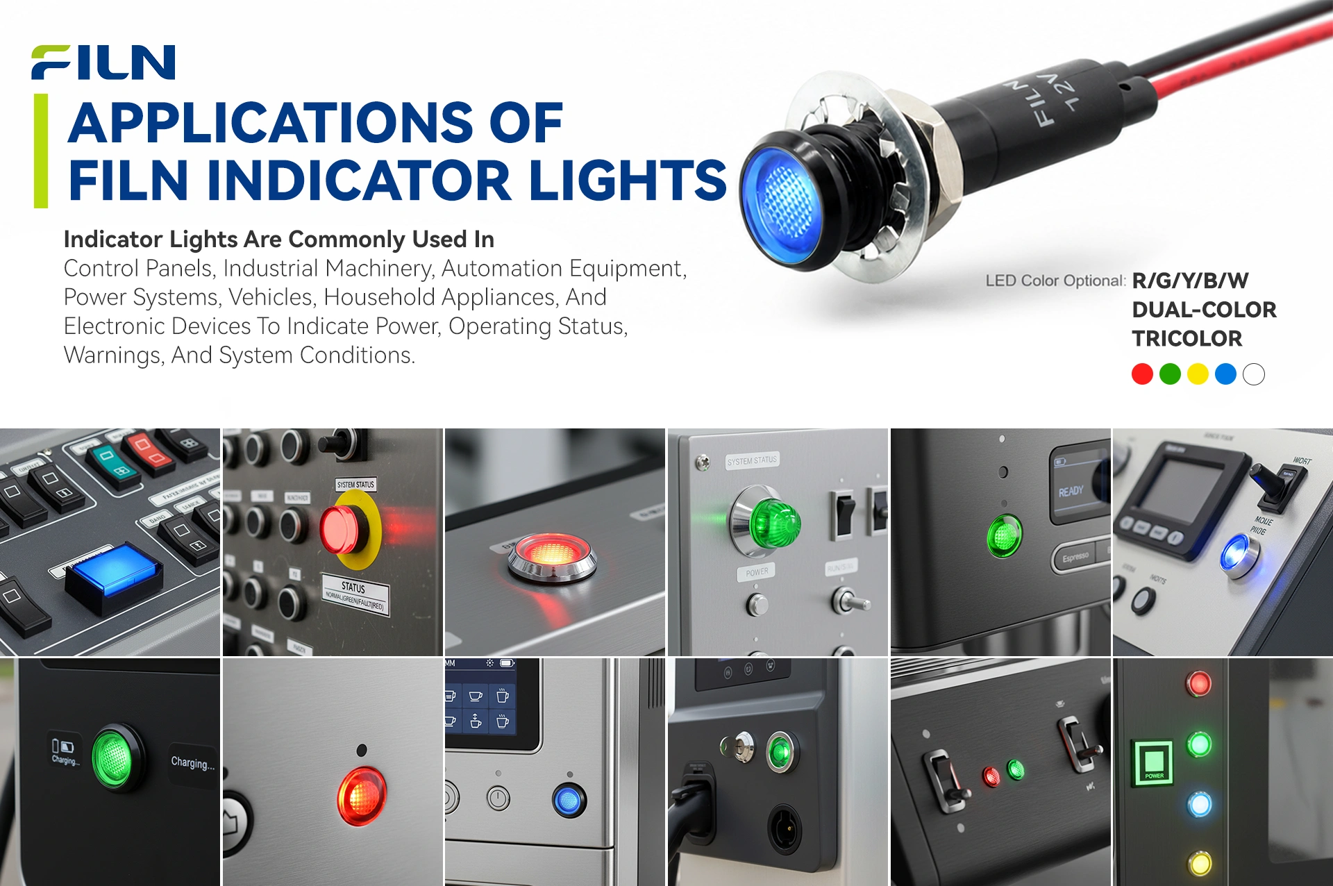
Engineered with a robust copper alloy or stainless steel chassis, FILN heavy-duty metal indicators are optimized to maintain sealing and visibility where conventional plastics degrade. Standard polymer indicators exposed to machine stresses undergo micro-fracturing, thermal deformation, and UV-aging. Conversely, metal pilot indicators resist continuous vibrations, fluid exposure, and mechanical impacts, providing reliability in modern industrial environments.
1. Industrial Automation & Machinery Manufacturing
Heavy machinery fields rely on metal status components due to continuous vibrations and exposure to oil residues. On CNC machining centers and metal lathe interfaces, red, yellow, and green metal indicator lights denote system processing, offline standbys, or emergency stop triggers while resisting cutting fluids and sharp flying metal shavings. For automation line control racks, space-efficient 6mm or 8mm indicators connect directly to AC 220V or DC 24V links to show power state updates. On large hydraulic pumps and pneumatic machinery systems, wire-integrated metal pilot configurations resist loose connections better than spade terminals under vibration conditions.
2. Outdoor Grid Infrastructure & Renewable Energy Distribution
Outdoor electrical hardware faces harsh exposure to solar radiation and wide temperature variations. Electric vehicle (EV) charging infrastructure uses concave metal status lights to communicate active charging, completion, or line fault ground errors. The IP67 chassis resists rain and public vandalism. In solar power grid combiner enclosures and municipal power distribution grids, these indicators operate reliably across an extended thermal range from -40°C to +80°C, ensuring visibility even under intense ambient sunlight.
3. Transit Systems, Engineering Vehicles & Marine Controls
Transit systems require high shock absorption and resistance to corrosion. Heavy-duty excavators, transport vehicles, and mobile cranes utilize metal instrument panels to signal fluctuating fluid pressures, core engine temperatures, and braking alerts under dusty conditions. For marine bridges and harbor distribution gear, chrome or stainless steel indicators resist salt fog corrosion while silicone sealing rings block sea water ingress.
4. Self-Service Commercial Terminals & Public Safety Systems
Public systems require physical protection against unauthorized tampering. Vending kiosks, ticketing equipment, and ATM interfaces match high-strength metal buttons with corresponding indicator lamps to display cash verification and item drop status. In hazardous environments like fuel dispensing terminals, the solid metal casing isolates electrical arcs to prevent gas ignition risks. For building access control stations, metal-framed status lights indicate secure or bypass states while resisting physical vandalism.
5. Medical Instruments & Food Processing Equipment
Sanitary processing industries use high-pressure hot water and chemical washdowns daily. IP67-sealed metal indicators resist corrosion from chemical sanitizers on food filling assemblies and packaging systems. Similarly, medical sterilization equipment and cleanroom workstations use these components to track heating, vacuum, and venting stages without risking lens clouding or material degradation.
Chromatic Signaling Logic & Operational Psychology
Industrial visual signaling relies on standardized color protocols to ensure rapid operator response and safety. Red indicators consistently denote critical conditions, emergency shutdowns, or immediate safety hazards. This color has the longest visible wavelength, enabling rapid perception over distance, and is reserved for conditions requiring immediate human intervention to prevent system failure or injury.
Green indicators communicate normal operation, completed sequences, or safe environments. This provides immediate visual confirmation that systems are functioning within established parameters. Yellow or amber indicators function as warning signals, identifying parameters that have breached standard limits, such as thermal thresholds or pressure drops, without indicating immediate failure. This alerts technicians to perform maintenance before a critical shutdown occurs.
Blue indicators denote mandatory technical actions, such as manual system resets, component changes, or pre-start configuration verification. This color differentiates operational instructions from standard system status alerts. White illumination serves as a neutral status indicator, typically showing that main grid power is active, incoming line tension is stable, or a specific process cycle is currently running.
To streamline modern complex panels, FILN engineers high-density bi-color and tri-color LED indicator systems. These configurations combine multiple emitter dies within a single 8mm metal housing, allowing a single panel location to transition across different color profiles, such as Red/Green or Red/Yellow/Green. This multi-state signaling capability reduces necessary panel space, simplifies wiring layouts, and lowers total component costs for system integrators.
Step-by-Step Mechanical Installation
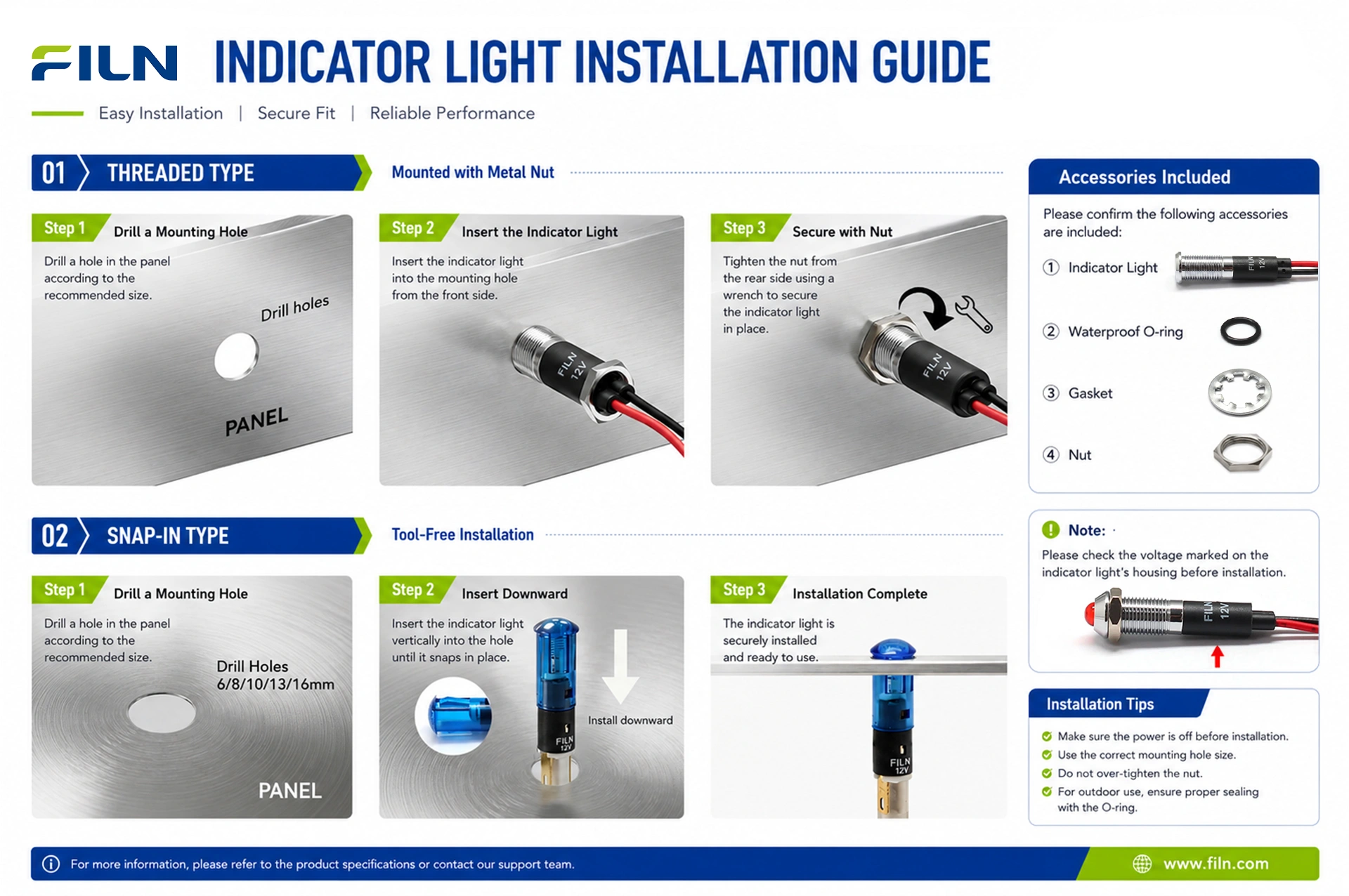
- Execute Panel Cutout: Using a calibrated punch tool or step drill bit, execute a precise 8.0mm diameter circular mounting aperture into the target console panel layer. Ensure the cutout boundaries are smooth and deburred.
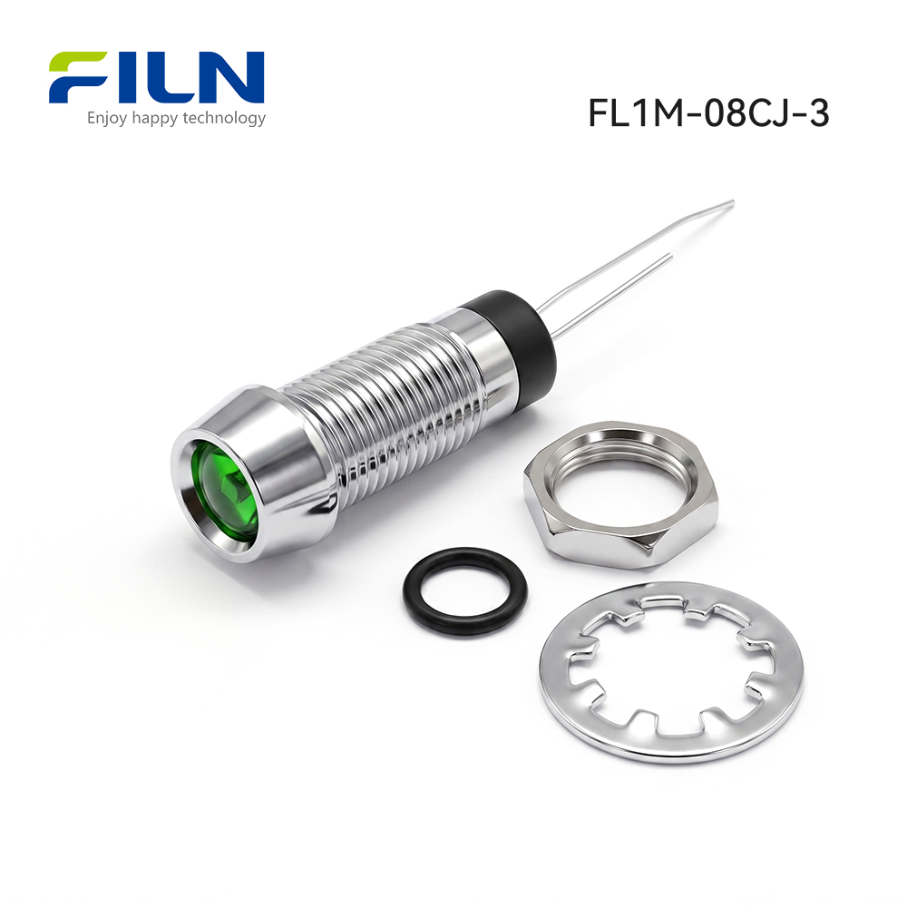
- Prepare Indicator Core Geometry: Ensure the retention hexagonal metal M6 nut and stainless steel lock washer are removed from the lower threaded barrel of the indicator, leaving only the primary silicone sealing ring seated flush against the upper flange bezel.
- Insert the Component Housing: Guide the lower termination barrel of the indicator downward into the 8mm cutout aperture from the front exterior surface of the control board panel face.
- Apply Rear Compression Hardware: Slide the star-profile stainless steel locking gasket followed by the matching mechanical hex nut over the bottom pins onto the threaded chassis barrel from behind the panel.
- Torque Retention Fasteners: Utilizing a matched box wrench tool, torque the hex nut firmly until the frontline silicone ring compresses uniformly against the panel skin, achieving an IP67 hermetic fluid seal. Avoid over-torqueing to prevent gasket displacement.
- Complete Electrical Wiring Termination: Connect the 2PIN termination pins to the supply circuit rails utilizing insulated female spade receptacles or direct lead soldering techniques.
Electrical Termination & Wiring Protocols
The electrical installation of industrial indicator lights depends on the specified connection interface. In 2PIN terminal pin models, external circuit leads are joined directly to the solid brass alloy pins. This connection is secured by manual rosin-core soldering or by sliding insulated quick-disconnect terminal sleeves over the pins. This solid-pin design provides high rigidity, preventing the internal wire shifting that can occur inside crowded electrical enclosures during maintenance.
For pre-wired direct wire-lead indicator variants, connections to internal circuit rails are made using quick-splice lever blocks, crimp-style butt splices, or twisted lineman splices insulated with heavy-duty heat-shrink tubing or industrial-grade electrical vinyl tape. Direct wire-lead configurations streamline high-speed automated wiring setups and eliminate field soldering requirements.
Prior to executing any electrical termination protocols, technicians must confirm the main circuit breaker is opened and locked out following standard OSHA Lockout/Tagout (LOTO) procedures. Verify the system is de-energized with a calibrated voltmeter to prevent electrical shock or damage to components.
Industrial Knowledge Center & Engineering Matrix
A common challenge when integrating low-voltage 24v led panel indicator lights into industrial control grids is the occurrence of residual voltage illumination, or faint glowing. This issue happens when leakage currents from long wire runs, solid-state PLC output leakage, or induction cross-coupling feed small voltages into high-efficiency LED chips. Because these solid-state emitters require minimal current to illuminate, they may glow faintly even when the control circuit is off. FILN resolves this issue by integrating custom-engineered leakage bypass resistors or Zener clamping diodes within the indicator body, ensuring the LED illuminates only when the circuit reaches full operational voltage.
Comparative Matrix: Termination Configurations
| Interface Type |
Engineering Benefits |
Design Disadvantages |
| Solid 2PIN Terminal |
Provides a rigid, high-temperature soldering point; compatible with quick-connect sleeves; prevents wire-pull stress inside panels. |
Requires manual assembly tooling or specialized soldering techniques on-site. |
| Direct Wire Lead |
Speeds up field installation via quick crimping blocks; eliminates local soldering requirements; fully sealed wire exit point. |
Wire lengths are fixed at manufacturing; requires wire routing space within the enclosure. |
| Screw Terminal Clamps |
Allows quick field maintenance using standard screwdrivers; no specialized terminal connectors required. |
Requires larger housing configurations; vulnerable to backing out under continuous machine vibration. |
B2B Buyer Sourcing & Decision Guide
Procurement teams specifying components for industrial applications must balance technical performance against cost efficiency. When evaluating metal indicator lights, review the material specifications carefully. Standard chrome-plated copper alloys offer a balance of mechanical strength and corrosion resistance for typical factory automation environments. For high-corrosion applications, such as marine control systems or chemical processing installations, specify premium stainless steel housings to ensure long-term stability.
Verify that electrical configurations match the intended power infrastructure. While 24V configurations are standard in modern PLC networks, check the schematic requirements for voltage variances. FILN supports custom engineering modifications, enabling production lines to build indicators tailored for inputs ranging from 3V to 220V. This customization reduces the need for external drop resistors or power-stepping hardware, simplifying the overall bill of materials (BOM).
Cross-Reference Recommendations & Alternate Product Form Factors
- Standard 8mm Wire Lead Metal Indicator (Model FL1M-08CW-1): Optimized for 120V system applications — View Technical Datasheet
- Standard 8mm Pin Terminal Metal Indicator (Model FL1M-08CJ-1): Configured for standard 120V mains control configurations — View Engineering Specifications
Why Design Engineers Specify FILN Components
FILN provides factory-direct sourcing to simplify supply chain management for global manufacturing entities. Operating as a direct manufacturer rather than a trading middleman, FILN offers flexible production options, including zero Minimum Order Quantity (MOQ) requirements for standard product lines. This approach supports rapid prototyping, system testing, and full-scale production runs without requiring excess component inventory.
The company maintains control over lead times by managing an integrated supply network. Specialized engineering teams handle custom configurations, from unique wire harness modifications to specialized electrical tuning, providing functional 3D CAD modeling files for quick design validation. Combined with globally recognized product certifications, FILN supports OEM buyers and automation system integrators in maintaining reliable build schedules.
Factory Direct Supply & Manufacturing Capabilities
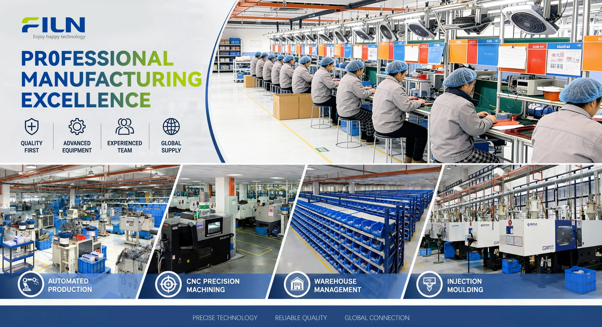
Established in 2006, Yueqing Yulin Electronic Co., Ltd. (FILN brand) operates from Wenzhou, Zhejiang, as an electrical switch manufacturer integrating R&D, manufacturing, and international sales. The company serves industrial markets across more than 100 countries, operating a modern 10,000 m² production facility equipped with 20 advanced automated production lines and a dedicated quality testing lab. Following the ISO9001 quality management framework, FILN monitors all manufacturing stages to verify product longevity and stable electrical parameters.
The company’s core product catalog includes panel indicator lamps, specialized pushbutton switches, rocker switches, and toggle switches. FILN maintains multiple product certifications, including ISO9001, CE, VDE, RoHS, SGS, UL, IP65, TUV, and CCC, ensuring compliance for deployment in residential appliances, green energy systems, automotive setups, marine electronics, and commercial power networks. Dedicated engineering specialists collaborate with procurement clients to design, prototype, and manufacture custom solutions for complex application requirements.
For additional technical parameters, visit the official corporate portal at www.filn.com. Engineering inquiries and request for quote (RFQ) submissions can be directed to the direct inbox at inquiry@cnylin.com.cn.
Frequently Asked Questions (Technical & Commercial)
1. How do you prevent phantom illumination (faint glowing) in 12v or 24v LED indicators?
Phantom illumination is caused by induction currents or PLC leakage voltage. FILN addresses this by integrating custom leakage bypass resistors inside the housing, suppressing stray currents to ensure the indicator illuminates only upon receiving full operational voltage.
2. Can this IP67 indicator light be washed down with caustic chemicals?
Yes. The combination of chrome-plated copper or anodized zinc-aluminum with a polycarbonate lens resists typical industrial chemical washdowns and sanitizing agents, outlasting standard plastic alternatives.
3. What is the standard lead time for a bulk wholesale order of custom voltage indicators?
Standard configurations are typically completed within 7 to 15 working days, depending on batch sizing and specific wire harness requirements.
4. Does FILN impose a Minimum Order Quantity (MOQ) for custom 8mm indicator runs?
No. FILN maintains zero MOQ limits for standard catalog designs and provides low thresholds for customized engineering orders to assist clients with prototyping.
5. How does the concave head geometry compare to flat or prominent head styles?
The concave head configuration sets the lens within a raised metallic bezel. This protects the optical component from oblique physical impact and focuses light directly forward to reduce side-angle glare.
6. What certifications apply to the FILN FL1M-08CJ-3 metal indicator product group?
This series is certified under CE, VDE, RoHS, CCC, and ISO9001 frameworks, meeting standard international regulatory requirements.
7. Are 2PIN solder terminals compatible with quick-connect wire receptacles?
Yes, the pin dimensions are engineered to receive standard quick-slide female terminal crimps or direct wire soldering.
8. Can these indicators run on alternating current (AC) power lines directly?
Yes. Internal bidirectional circuit adjustments allow these indicators to run on either AC or DC current across specified operating voltages.
9. What is the thermal operational boundary for these industrial indicator lights?
The verified safe operating range is from -40°C up to +80°C, allowing for use in cold storage facilities and high-temperature machinery environments.
10. Why is the carbon film resistor preferable over generic resistance wire coils?
Carbon film resistors offer stable thermal dissipation and consistent resistance characteristics, protecting the internal LED from unexpected electrical surges.
11. What mounting options secure the indicator against high mechanical vibration?
The indicator is secured using an integrated stainless-steel star locking washer that grips the back of the panel skin under the tension of the M6 hex nut.
12. How can I obtain 3D STP files for layout verification in SolidWorks?
Contact the engineering department via email at inquiry@cnylin.com.cn to request the relevant CAD files.
13. What is the typical operating life of a solid-state indicator running continuously?
The integrated LED core delivers an operational life between 50,000 and 100,000 hours, minimizing regular maintenance requirements.
14. Are white LED options color-calibrated to match distinct color temperatures?
Yes, FILN white LED elements follow standard CIE chromaticity specifications to ensure uniform output across different manufacturing lots.
15. Does the black-anodized alloy option flake or chip over time?
No, the anodization process integrates the oxide layer into the zinc-aluminum body, preventing the peeling or flaking common with external paint finishes.
16. What thickness of enclosure steel can the 8mm threaded body accommodate?
The threaded barrel length is designed to fit standard industrial panels up to 6mm thick while maintaining proper gasket seal compression.
17. Are sample units provided free of charge for industrial design evaluation?
Yes, engineering samples are provided to qualified OEMs and system integrators upon submitting an application to our sales team.
18. Is PA66 material safe from outgassing in high-temperature applications?
Yes, the high-grade polyamide nylon PA66 retains structural stability and flame retardancy up to standard electrical operating limits.
19. Can FILN assemble custom wire configurations directly onto the 2PIN terminals?
Yes, our automated assembly lines can integrate wire leads and connectors to streamline field installation for large production series.
20. How do I initiate a direct technical inquiry with an electronics design engineer?
Submit your circuit diagrams and design specifications to inquiry@cnylin.com.cn to connect with our engineering department.