KEY TAKEAWAYS FOR INDUSTRIAL BUYERS
- Heavy-Duty Construction: Features a rugged metallic housing that surpasses standard plastic housing options in impact strength and thermal resistance.
- Pre-Wired Efficiency: Factory integrated 2PIN wire leads eliminate terminal soldering steps, reducing control cabinet assembly time significantly.
- Environmental Sealing: Achieves IP67 ingress protection using an internal silicone O-ring seal to prevent fluid penetration.
- Wide Voltage Versatility: Standard and custom internal current-limiting resistor configurations support operating voltages from 3V to 220V AC/DC.
- Global Compliance Credentials: Officially certified under UL (E498776), CE, VDE, RoHS, CCC, and ISO9001 requirements for international deployment.
- Flat Profile Design: Low-profile flat head aesthetic prevents accidental impact damage on dense operator panel surfaces.
- Extended Operating Life: Premium chip encapsulation ensures 50,000 to 100,000 continuous operating hours with minimal luminous decay.
- Factory Direct Flexibility: Direct purchasing from FILN allows custom lead lengths, terminal additions, wire gauges, and rapid sample delivery.
WHAT IS A RED INDICATOR LIGHT
A red indicator light is an electro-optical visual signaling component mounted on equipment operator panels to communicate critical system states, power conditions, fault warnings, or operational stops. Utilizing solid-state light-emitting diode technology encased within a protective housing, a red indicator light converts electrical signals into bright optical output visible from significant distances in high-ambient lighting environments.
In industrial control systems, selecting the correct red indicator light structure depends on structural durability and wiring requirements. Industrial signal indicators fall into two main categories: plastic indicators and metallic indicators. Plastic models suit light-duty indoor applications, while metallic models provide superior physical strength, chemical shielding, and resistance to environmental degradation across mounting cutouts ranging from 6mm to 30mm.
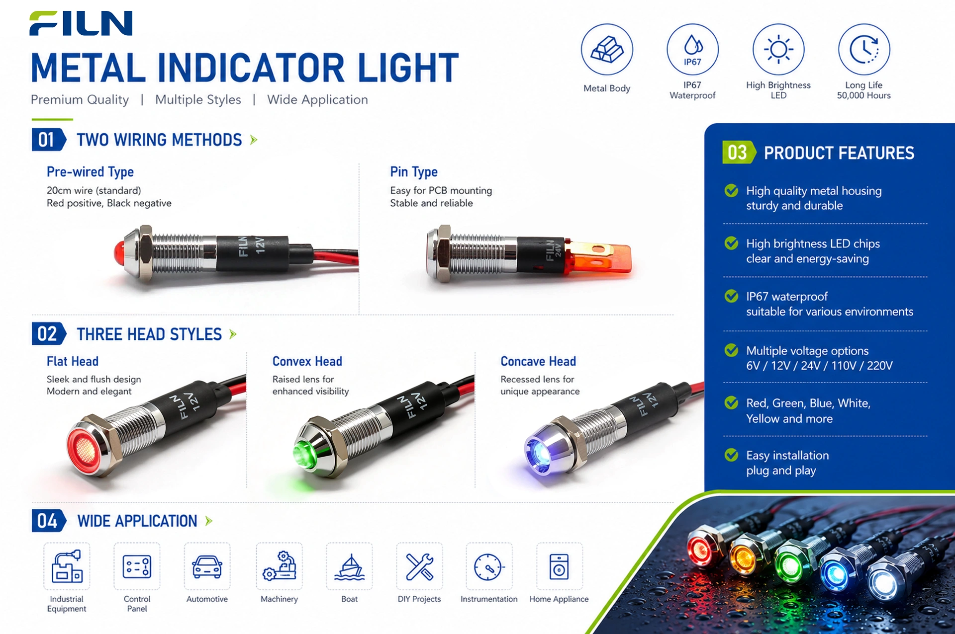
Wiring configurations include pin-type quick-connect terminals and pre-wired wire lead constructions. Pre-wired designs seal internal electrical connections inside the metal body, safeguarding joints against dust and moisture ingress. For physical profiles, engineers can choose between flat head, prominent head, and concave head geometries to meet specific panel ergonomics and side-angle visibility standards.
PRODUCT OVERVIEW: FL1M-12FW-1 RED INDICATOR LIGHT
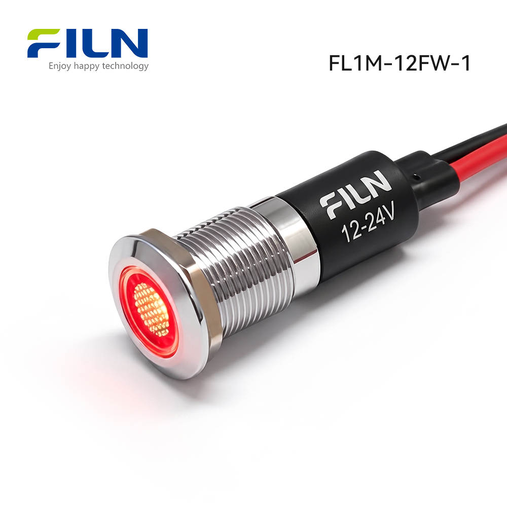
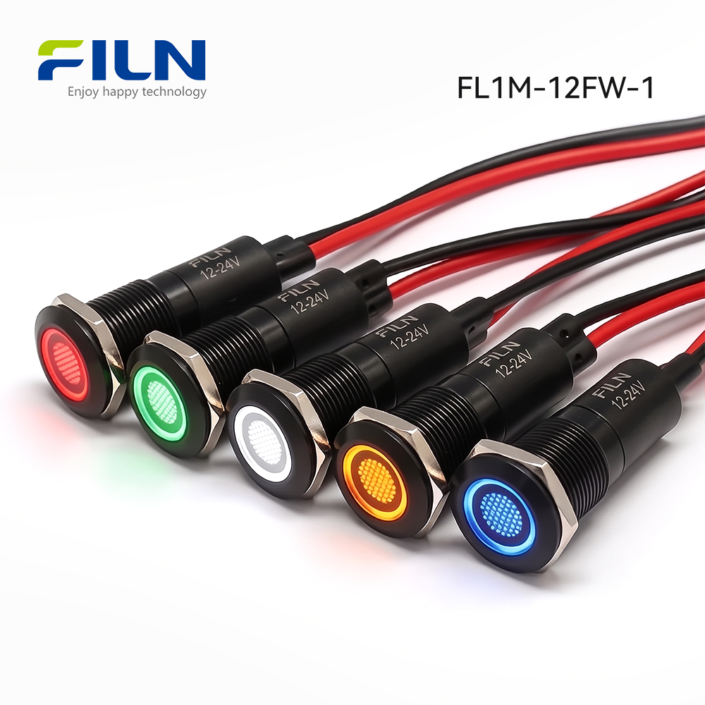
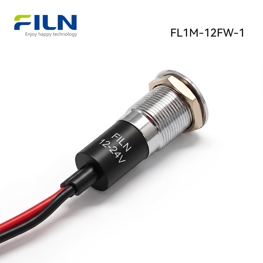
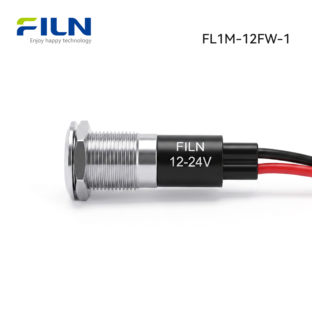
The FL1M-12FW-1 red indicator light features a compact 12mm thread diameter, making it ideal for high-density electrical panel layouts. Constructed with a precision-machined brass alloy housing finished in bright chrome or black plating, this red indicator light offers structural integrity that far exceeds standard polycarbonate alternatives in high-vibration, high-impact industrial installations.
Electrically, the unit contains a high-efficiency red LED chip combined with a internal current-limiting carbon film resistor. When energized across its designated terminal potential, the assembly produces uniform, non-glare circular illumination through a polycarbonate diffuser lens. This design provides immediate status recognition while drawing less than 20mA of continuous operating current.
Featuring factory-attached 2PIN wire leads, the unit simplifies field wiring by permitting direct connections through terminal blocks or inline pressure connectors. Backed by UL, CE, and RoHS certifications, this red indicator light is widely integrated into industrial automation panels, power distribution equipment, commercial machinery, and marine electrical enclosures requiring IP67 ingress protection.
QUICK TECHNICAL SPECIFICATIONS
| Specification Parameter |
Technical Specification Data |
| Product Description |
Metal red indicator light with pre-wired lead cables |
| Model Number |
FL1M-12FW-1 |
| Mounting Hole Cutout |
12 mm / 0.472 inches |
| Operating Voltage Options |
3V, 6V, 12V, 24V, 36V, 110V, 220V AC/DC (Customizable) |
| Illumination Color |
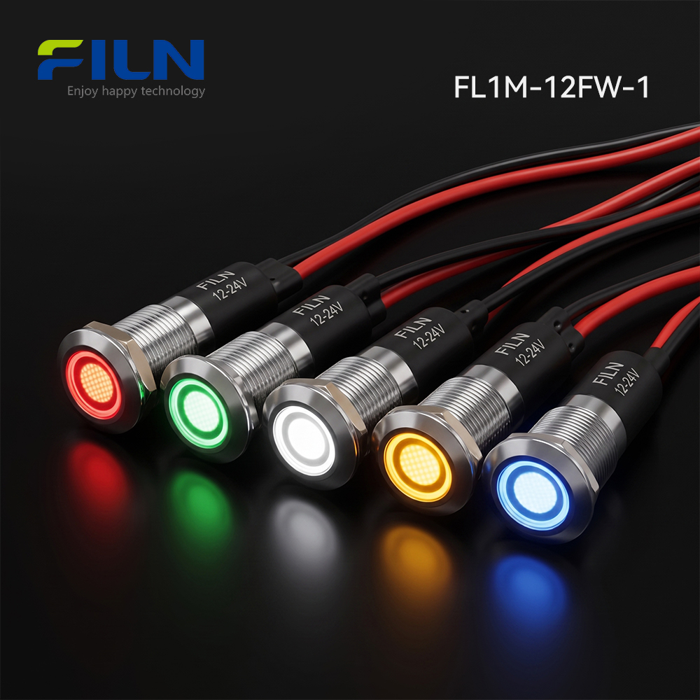
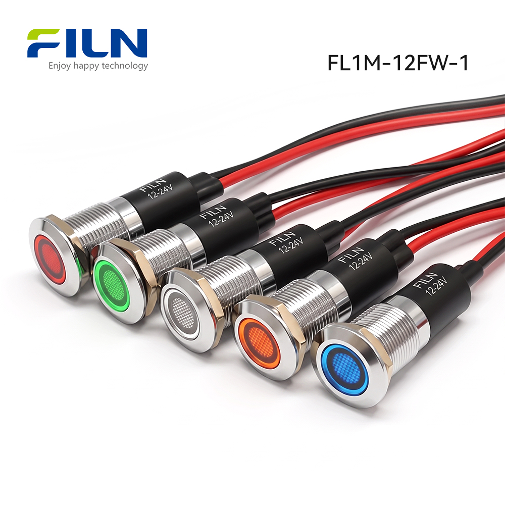
Red, Green, Yellow, Blue, White, Bi-color, Tri-color |
| Waterproof Ingress Protection |
IP65 / IP67 Rated |
| Termination Type |
2PIN Pre-wired lead type (Standard 200mm cable) |
| Head Shape Design |
Flat head configuration |
| Surface Finish Standards |
Smooth metallic finish, burr-free, anti-oxidation plating |
| Included Hardware Accessories |
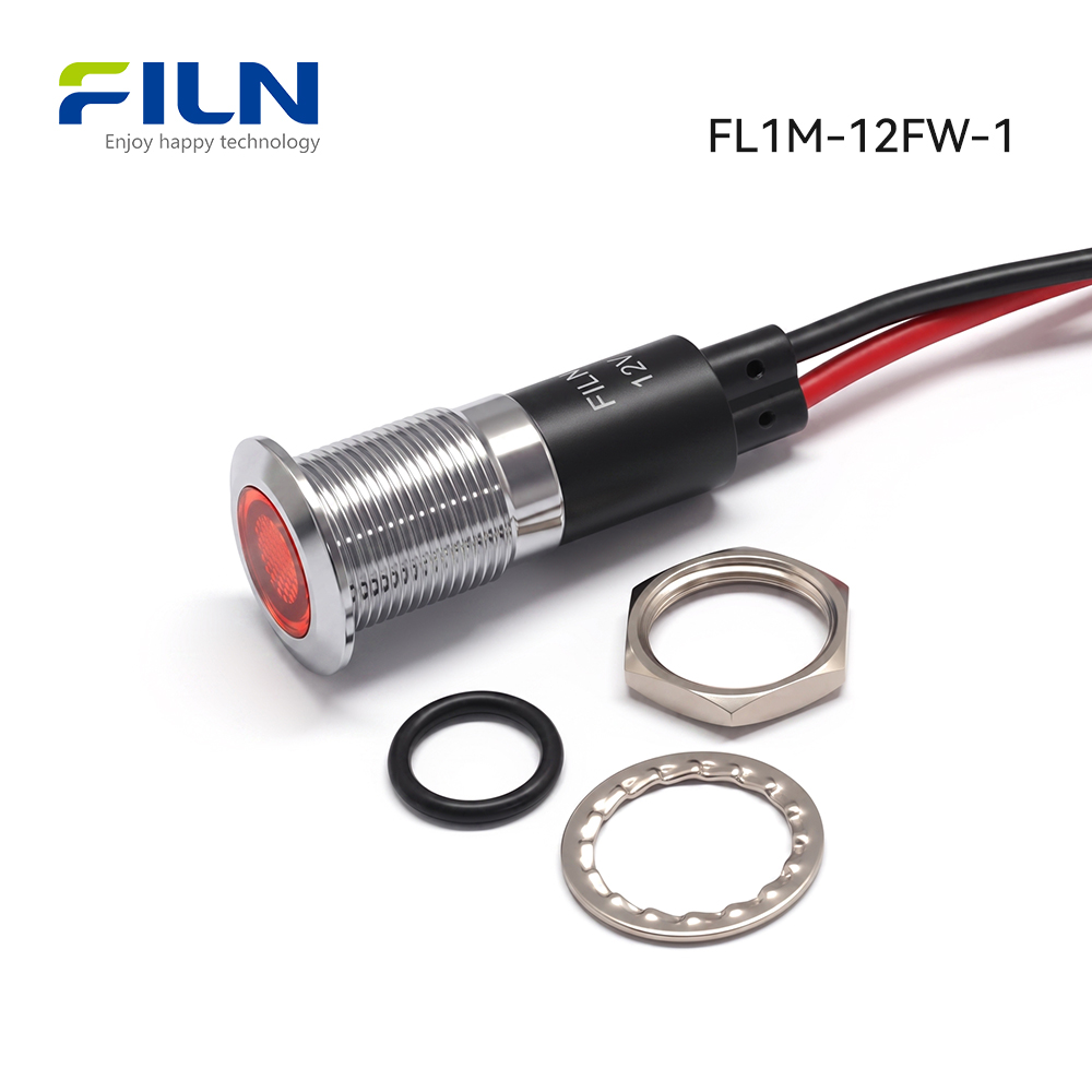
1x Indicator body, 1x Silicone O-ring, 1x Stainless gasket, 1x M12 Nut |
ELECTRICAL & MECHANICAL PERFORMANCE PARAMETERS
| Performance Rating Category |
Engineering Parameter Value |
| Rated Operating Voltage Range |
3V – 240V DC/AC (Custom factory tolerances available) |
| AC Operating Frequency |
50 Hz / 60 Hz |
| Rated Operating Current |
≤ 20 mA at rated operational potential |
| Power Consumption |
Approx. 0.2 Watts |
| Insulation Resistance |
≥ 100 MΩ (Tested at 500V DC between conductor and housing) |
| Dielectric Strength Voltage |
1500V to 1800V AC for 1 min (No flashover or breakdown) |
| Continuous Working Lifespan |
50,000 to 100,000 Hours continuous operation |
| Ingress Protection Rating |
IP67 Water and dust immersion resistant |
COMPONENT MATERIALS & ENGINEERING RATIONALE
| Component Name |
Selected Material Grade |
Engineering Advantage & Material Selection Rationale |
| Outer Shell Housing |
Nickel-plated Copper Alloy / Black Zinc Alloy |
Provides high mechanical strength, corrosion shielding, and aesthetic panel integration. |
| Internal Lamp Base Holder |
Flame-Retardant PA66 Nylon |
Offers high dielectric insulation and elevated thermal tolerance inside control units. |
| Lampshade Diffuser Lens |
Optical Polycarbonate (PC) |
Delivers high impact resistance and uniform red light dispersion without hotspots. |
| Luminescent Source |
Ultra-Bright Semiconductor LED |
Ensures maximum luminous intensity with minimal thermal output and low power drain. |
| Internal Voltage Resistor |
Carbon Film Resistor Assembly |
Regulates drive current across designated voltage limits to protect LED junction. |
| Output Wiring Leads |
High-Grade Flexible PVC Wires |
Guarantees electrical insulation and flexible routing inside compact electrical enclosures. |
| Panel Mounting Hex Nut |
Machined Copper Alloy |
Provides precise thread engagement to prevent loosening under equipment vibration. |
| Sealing Waterproof O-Ring |
High-Grade Silica Gel (Silicone) |
Forms an elastic seal against metal panels to achieve reliable IP67 moisture sealing. |
| Lock Washer Gasket |
Stainless Steel Plum Blossom Gasket |
Maintains constant compression tension against panel surfaces to resist rotational movement. |
ENVIRONMENTAL TESTING & RELIABILITY STANDARDS
This engineering test specification applies across the FILN metal red indicator light series. Environmental testing verifies that panel indicators operate reliably under severe temperature fluctuations, elevated humidity, and harsh weather conditions.
| Test Parameter |
Environmental Test Conditions & Criteria |
| Operating & Storage Temperature |
-40°C to +80°C continuous ambient temperature |
| Operating Relative Humidity |
≤ 85% RH at +40°C ambient temperature |
| High Temperature Resistance Test |
Subjected to 80°C ± 2°C for 96 continuous hours without material deformation |
| Low Temperature Resistance Test |
Subjected to -40°C ± 2°C for 96 continuous hours without structural cracking |
| Constant Temp & Humidity Chamber |
96 hours at +40°C ± 2°C with 90% to 95% relative humidity testing |
| Thermal Shock Temperature Cycling |
5 cycles: Alternate between -40°C (30 min) and +85°C (30 min) |
LED OPTICAL & ELECTRO-TECHNICAL DATA
1. Absolute Maximum Ratings (Ta = 25°C)
| Electro-Optical Characteristic |
Symbol |
Absolute Maximum Value |
| Max Forward DC Current |
IFP |
20 mA |
| Peak Reverse Voltage Protection |
VR |
5 V |
| Power Dissipation Limit |
PD |
60 mW |
| Operating Ambient Temperature |
TOPR |
-40°C to +80°C |
| Storage Temperature Range |
TSTG |
-40°C to +100°C |
| Lead Soldering Temperature Limit |
TSOL |
Max. 260°C for 3 sec maximum |
2. Electro-Optical Characteristics (Ta = 25°C)
| Parameter Description |
Test Conditions |
Min Value |
Typ Value |
Max Value |
| Forward Voltage Drop (VF) |
IF = 20mA |
2.8 V |
3.0 V |
3.2 V |
| Reverse Current Leakage (IR) |
VR = 5V |
— |
— |
5 μA |
| Viewing Angle (2θ½) |
IF = 20mA |
— |
60° |
— |
| Luminous Intensity (Iv) |
IF = 20mA |
500 mcd |
650 mcd |
800 mcd |
| Dominant Wavelength (λd) |
IF = 20mA |
620 nm |
623 nm |
625 nm |
| Junction Temperature (Tj) |
IF = 20mA |
— |
— |
125°C |
| Thermal Resistance (RJP) |
IF = 20mA |
— |
8 °C/W |
— |
LABORATORY TEST ENVIRONMENT STANDARDS
Unless explicitly noted otherwise in specific engineering test sheets, all optical, electrical, and lifespan properties of the red indicator light are measured in laboratory conditions under strict atmospheric parameters:
| Environmental Test Variable |
Standard Atmospheric Range |
| Ambient Test Temperature |
5°C to 35°C |
| Relative Test Humidity |
45% to 85% RH |
| Atmospheric Barometric Pressure |
86 kPa to 106 kPa (860 mbar to 1060 mbar) |
Technical Note: Luminous intensity and dominant optical wavelength measurements are calibrated in full accordance with CIE international standard eye response curves. The allowable measurement tolerance for luminous intensity is ±15%, and voltage measurement tolerance is ±0.1V.
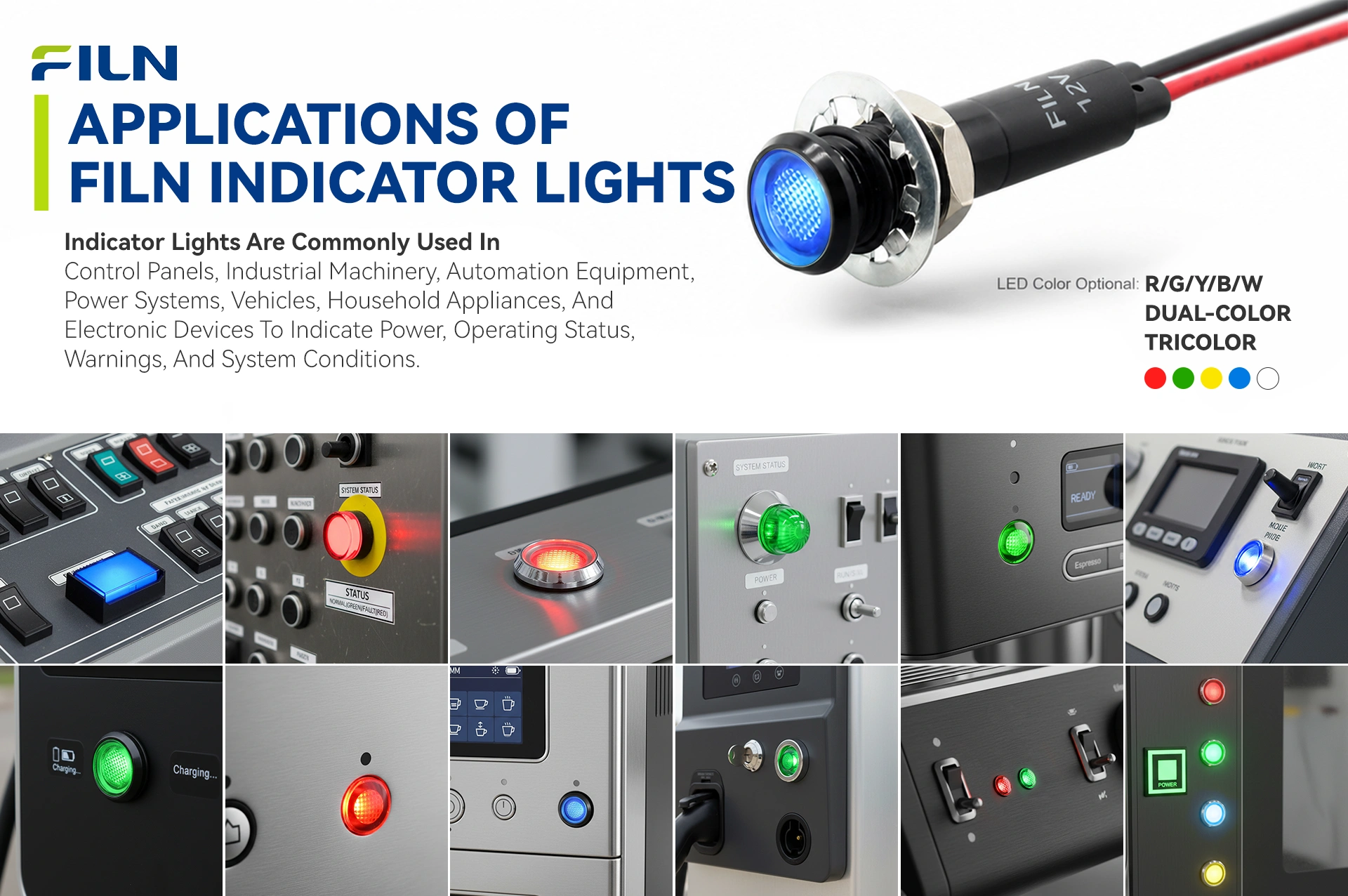
INDUSTRIAL APPLICATIONS & DEPLOYMENT SCENARIOS
Featuring high-strength copper alloy or stainless steel metallic bodies, metallic indicator lights provide impact protection and IP67 waterproof-dustproof sealing. While standard plastic indicator lamps suffer from ambient UV discoloration, cracking, and thermal deformation over extended operation, metal indicator units are purpose-built for heavy industrial duties, high-vibration applications, and continuous operation.
1. Industrial Automation & Machinery Manufacturing
This sector represents the primary deployment environment for metallic indicators. Metal housings withstand cutting fluids, oil mist, and physical impacts from loose tools inside workshop environments:
- CNC Machining Centers: Mounted on panel interfaces to display status; red signaling indicates emergency shutoff, feed hold, or drive faults.
- PLC Control Cabinets: Installed on power distribution panels (6mm, 8mm, 12mm sizes) running 24V DC or 220V AC to indicate circuit power states.
- Hydraulic & Pneumatic Units: Monitors pump operation and pressure over-limit alerts; pre-wired leads eliminate lead fatigue caused by machinery vibration.
2. Outdoor Power & Renewable Energy Systems
Outdoor installations demand resistance to wide temperature swings and UV exposure:
- EV Charging Stations: Flat-head metal indicator lights signal charging states (flashing red indicates ground faults or leakage).
- Solar Combiner Boxes: Mounted on solar array control units to signal high-voltage breaker states across ambient temperatures from -40°C to +80°C.
3. Rail Transit, Heavy Vehicles & Marine Gear
Designed to handle severe dynamic shock, salt spray, and vibration:
- Construction Machinery Dashboards: Provides immediate oil pressure and brake system warnings in excavator cabins.
- Marine & Deck Controls: Stainless steel bodies resist salt spray corrosion and prevent water ingress behind control consoles.
4. Commercial Self-Service & Public Access Equipment
Vandal-resistant construction protects public-facing hardware:
- Vending & Ticketing Kiosks: Integrates alongside vandal-resistant pushbuttons to indicate payment processing or system fault states.
- Fueling Dispenser Panels: Provides physical electrical isolation in hazardous fuel vapors.
5. Medical & Food Processing Machinery
Hygienic processing environments require sealed designs that can withstand frequent chemical washdowns:
- Food Packaging Lines: Withstands daily high-pressure hot water and chemical washdown cycles without seal degradation.
- Sterilization Equipment: Indicates high-temperature autoclave phases cleanly and reliably.
INDICATOR LIGHT COLOR CODES & FUNCTIONAL MEANINGS
Standard industrial human-machine interfaces rely on standard visual signal color schemes to ensure immediate operator comprehension. FILN manufactures single-color, bi-color, and tri-color indicator units to support varying panel requirements:
| Color |
Standard Functional Meaning |
Typical Application Scenario |
Engineering Rationale |
| Red (R) |
Danger, Fault, Emergency Stop |
System failure, over-temperature alert, emergency state |
Demands immediate operator intervention; universally associated with danger. |
| Green (G) |
Normal Operation, Ready, Safe |
Motor running, system healthy, line energized |
Signals active operation under controlled conditions without errors. |
| Yellow (Y) |
Warning, Caution, Standby |
Parameter threshold limit approached, maintenance due |
Prompts operator monitoring before conditions escalate into critical faults. |
| Blue (B) |
Mandatory Action, Specific State |
User reset required, blue-tooth connection status |
Used for dedicated status conditions non-critical to general safety alarms. |
| White (W) |
General Status, System Power On |
Main power active, secondary switch state confirmation |
Provides neutral illumination without signaling specific warning or safe states. |
FILN bi-color and tri-color indicator lamps combine multiple LED dies within a single housing. This allows a single 12mm panel cutout to switch between Red/Green or Red/Yellow/Green modes, saving panel space while delivering clear multi-state indication.
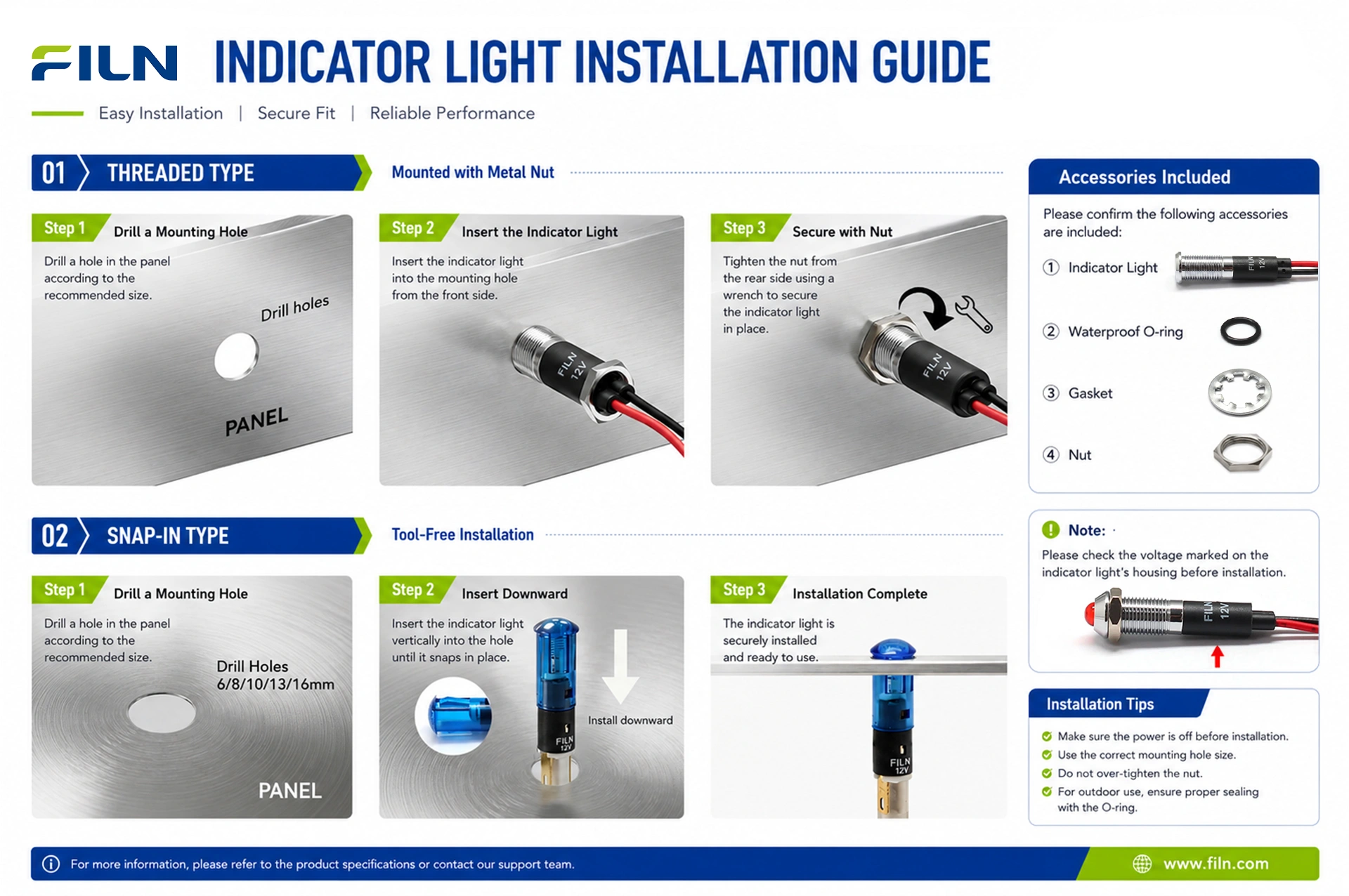
STEP-BY-STEP INSTALLATION GUIDE
Follow this installation procedure to ensure proper mechanical mounting and maintain an IP67 waterproof seal for your red indicator light:
- Panel Hole Preparation: Drill or punch a clean 12.0mm (0.47 inch) circular cutout through the panel face. Remove all metal burrs and debris from around the hole edges.
- Waterproof Seal Placement: Slide the silicone O-ring gasket over the red indicator light leads up to the flange on the metal head assembly.
- Front Panel Insertion: Insert the wire leads and threaded metal body through the front cutout of the enclosure until the silicone ring sits flush against the panel.
- Rear Lock Hardware Assembly: From behind the panel, slide the stainless steel plum blossom lock washer over the wires, followed by the M12 brass mounting nut.
- Torque Tightening: Hand-thread the M12 hex nut onto the casing. Tighten using an adjustable wrench to 1.5–2.0 Nm torque to compress the silicone washer without over-deforming it.
- Electrical Termination: Strip lead ends and connect the 2PIN wire leads into your control circuit terminal block or wire connectors, ensuring correct polarity for DC models.
WIRING METHOD COMPARISON & SAFETY PROCEDURES
When wiring a red indicator light, selecting the right connection method depends on your panel layout, environmental vibration levels, and maintenance preferences:
| Indicator Terminal Style |
Pros / Key Advantages |
Cons / Limitations |
Recommended Application Scope |
| 2PIN Wire Lead (FL1M-12FW-1) |
Direct connection via quick lever connectors, soldering, or crimp terminals; superior moisture sealing inside the body. |
Fixed factory wire length (custom lengths must be requested at time of order). |
High-vibration machinery, outdoor cabinets, IP67 washdown areas. |
| Solder Pin Terminal (FL1M-12FJ-1) |
Compact rear depth profile; allows direct wire soldering or custom plug-in connections. |
Requires manual field soldering; exposed rear solder joints require heat-shrink insulation. |
Ultra-shallow control boxes, PCB custom interface sub-assemblies. |
To order pin terminal models, visit the 12MM Pin Terminal Red Indicator Light FL1M-12FJ-1 Page.
Electrical Safety Warning: Always disconnect power before handling wiring connections. For pre-wired lead indicators, use lever quick connectors, soldered joints insulated with heat-shrink tubing, or high-grade electrical tape to maintain solid electrical conductivity and prevent short circuits.
INDUSTRY KNOWLEDGE BASE & TROUBLESHOOTING
Preventing Phantom Illumination (Faint Glowing)
Phantom illumination occurs when a red indicator light glows faintly even when switched off. This is typically caused by small leakage currents passing through solid-state relays, long parallel wiring runs (capacitive coupling), or PLC leakages. Because efficient red LEDs require very little energy to illuminate, even micro-amp currents can cause faint glowing.
Solution: Install a bleed resistor or a RC snubber circuit in parallel across the indicator leads to divert low-level leakage current around the LED assembly.
Common Troubleshooting Steps
- Indicator Fails to Illuminate: Check DC polarity alignment (red lead positive, black lead negative). Verify that the line voltage matches the rated indicator voltage.
- LED Burnout Upon Startup: Occurs when applying high line voltage (e.g., 110V/220V) to a low-voltage unit (e.g., 12V/24V) without an appropriate internal drop resistor. Verify input line levels before powering up.
- Water Ingress Behind Panel: Check that the silicone O-ring is seated correctly on the front face of the panel and that the M12 nut is tightened to spec.
B2B BUYER DECISION & SELECTION GUIDE
When specifying a red indicator light for high-volume manufacturing or infrastructure projects, evaluate the following parameters:
- Mounting Cutout Dimensions: Match panel cutout constraints. Standard sizes include 6mm, 8mm, 10mm, 12mm, 16mm, 22mm, and 30mm.
- Supply Voltage Match: Select matching ratings (12V DC, 24V DC, 110V AC, 220V AC) to avoid the need for external resistor networks.
- Environment Protection Standards: Ensure IP67 sealing for washdown, outdoor, or wet processing environments.
- Regulatory Certifications: Look for official UL, CE, and RoHS approvals to streamline final equipment export compliance.
Recommended Similar Indicator Products
WHY OEM ENGINEERS & PROCUREMENT DIRECTORS SPECIFY FILN
| Factory Direct Advantage |
Direct purchasing eliminates intermediary markups, offering competitive volume pricing for OEM buyers. |
| Flexible Order Quantities |
Zero minimum order quantity (No MOQ) supports prototyping and low-volume production runs. |
| Rapid Prototyping Lead Times |
Sample orders ship within 24–72 hours; custom product production cycles run under 7 days. |
| Full OEM / ODM Support |
Custom wire lead lengths, specialized connector crimping, laser-etched symbols, and dual-voltage designs. |
| In-House Testing Lab |
Every lot undergoes rigorous testing for insulation resistance, waterproofing, and luminous decay. |
FACTORY DIRECT MANUFACTURING & GLOBAL SUPPLY CAPACITY
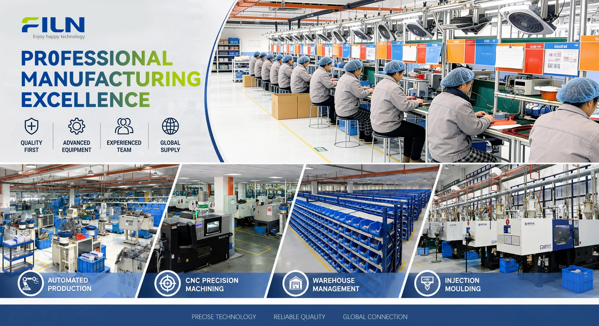
Yueqing Yulin Electronic Co., Ltd., operating globally under the FILN brand, was established in 2006 in Wenzhou, Zhejiang, as an electrical switch manufacturer integrating R&D, production, and sales. Today, premium FILN components are distributed across more than 100 countries. Operating out of a modern 10,000 m² facility with over 20 advanced automated production lines and an independent testing laboratory, FILN operates under ISO9001 quality management systems.
FILN certified product ranges (UL, CE, VDE, RoHS, REACH, TUV, CB) are widely specified across commercial kitchen appliances, battery energy storage, EV charging networks, automotive modifications, marine vessels, and industrial automation cabinets.
| Core Production Lines |
Indicator lights, metal pushbutton switches, rocker switches, toggle switches, custom wiring harnesses. |
| Quality System & Certifications |
ISO9001, CE, VDE, RoHS, SGS, UL (E498776), IP67, TUV certified. |
| Global Export Markets |
United States, Canada, Germany, United Kingdom, Australia, and over 100 countries worldwide. |
| Official Web Portal |
www.filn.com |
| Engineering Contact Email |
inquiry@cnylin.com.cn |
FREQUENTLY ASKED QUESTIONS (FAQ)
1. How to prevent phantom illumination (faint glowing) in 12v LED indicators?
Phantom illumination is caused by micro-leakage currents from solid-state relays or capacitive wire coupling. Installing a bleed resistor or snubber circuit in parallel across the indicator leads bypasses this residual voltage.
2. Can this IP67 indicator light be washed down with caustic chemicals?
Yes. The combination of a nickel-plated brass or stainless steel metallic housing, polycarbonate lens, and silicone seal withstands routine chemical washdowns in food processing and medical gear.
3. What is the official UL certificate number for this red indicator light?
The FILN metal indicator series is certified under UL Certificate Number E498776, verifying compliance with North American electrical standards.
4. What is the standard mounting hole diameter for model FL1M-12FW-1?
Model FL1M-12FW-1 requires a standard 12mm (0.472 inch) round panel cutout for proper installation.
5. Does this red indicator light require an external resistor for 220V AC operation?
No. High-voltage versions contain an internal carbon film current-limiting resistor, allowing direct connection across specified 110V or 220V AC terminals.
6. What is the standard wire length provided on the wire lead version?
Standard stock units feature 200mm (8 inches) pre-wired 2PIN PVC leads. Custom cable lengths and terminal connectors can be ordered directly from our factory.
7. How does a metallic indicator housing compare to a plastic housing?
Metallic bodies offer higher impact resistance, better chemical protection, and immunity to UV yellowing or embrittlement compared to plastic alternatives.
8. Can FILN supply customized wire lead configurations and connector plugs?
Yes. As a factory-direct manufacturer, FILN offers custom lead lengths, specialized wire jackets (silicone/Teflon), and pre-crimped terminal connectors.
9. What color options are available for the 12mm panel indicator series?
In addition to red, FILN manufactures green, yellow, blue, and white single-color units, as well as bi-color and tri-color LED configurations.
10. What is the expected continuous operating lifespan of the red LED chip?
The embedded high-brightness LED chip is rated for 50,000 to 100,000 hours of continuous operation under rated thermal and voltage parameters.
11. What head profiles are available for FILN 12mm metal indicators?
FILN offers flat head, prominent (convex) head, and concave head metal housing options to match varying panel aesthetics and visibility requirements.
12. Is there a minimum order quantity (MOQ) for custom sample evaluations?
No. FILN maintains a zero minimum order quantity policy (No MOQ) for standard and sample evaluation orders to assist design engineers.
13. What sealing component ensures the IP67 waterproof rating during panel mounting?
A high-grade flexible silicone O-ring sits between the panel face and the metallic indicator flange, creating an airtight, waterproof seal when torqued down.
14. What is the rated operating temperature range for this indicator component?
The indicator operates reliably across ambient environmental temperatures ranging from -40°C to +80°C.
15. What torque setting should be applied to the M12 rear locknut?
We recommend applying 1.5 Nm to 2.0 Nm torque to secure the rear hex nut tightly against the panel without damaging the internal threads or silicone seal.
16. Are 3D CAD models available for panel layout design?
Yes. STEP files, 3D CAD models, and dimensional engineering drawings are available upon request by contacting our engineering sales team.
17. How does the pre-wired version improve manufacturing assembly speed?
Pre-wired leads eliminate the manual pin soldering step on control cabinet assembly lines, saving time and reducing cold solder joint risks.
18. Which international quality management systems govern FILN manufacturing?
FILN production facilities operate under ISO9001 quality management standards, ensuring consistent production quality and full batch traceability.
19. Can DC version indicators operate on AC power lines directly?
Standard DC units require polarity-correct direct current. However, FILN offers bi-directional AC/DC universal models upon request.
20. How can industrial procurement buyers order wholesale red indicator lights?
Procurement teams can request direct factory price quotes, commercial terms, and custom production runs by emailing inquiry@cnylin.com.cn.